Rubber ring grinding device for float glass conveying roller way and grinding method
A conveying roller table and float glass technology, which is applied in the direction of grinding machines, grinding/polishing equipment, and machine tools designed for grinding the rotating surface of workpieces, etc. It can solve glass surface scratches, apron punctures, and affect the quality of glass products and other problems, to achieve the effect of simplifying the steps of grinding operations and ensuring the grinding accuracy
- Summary
- Abstract
- Description
- Claims
- Application Information
AI Technical Summary
Problems solved by technology
Method used
Image

Examples
Embodiment 1
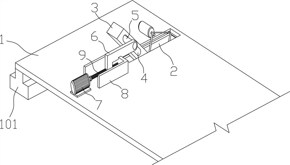
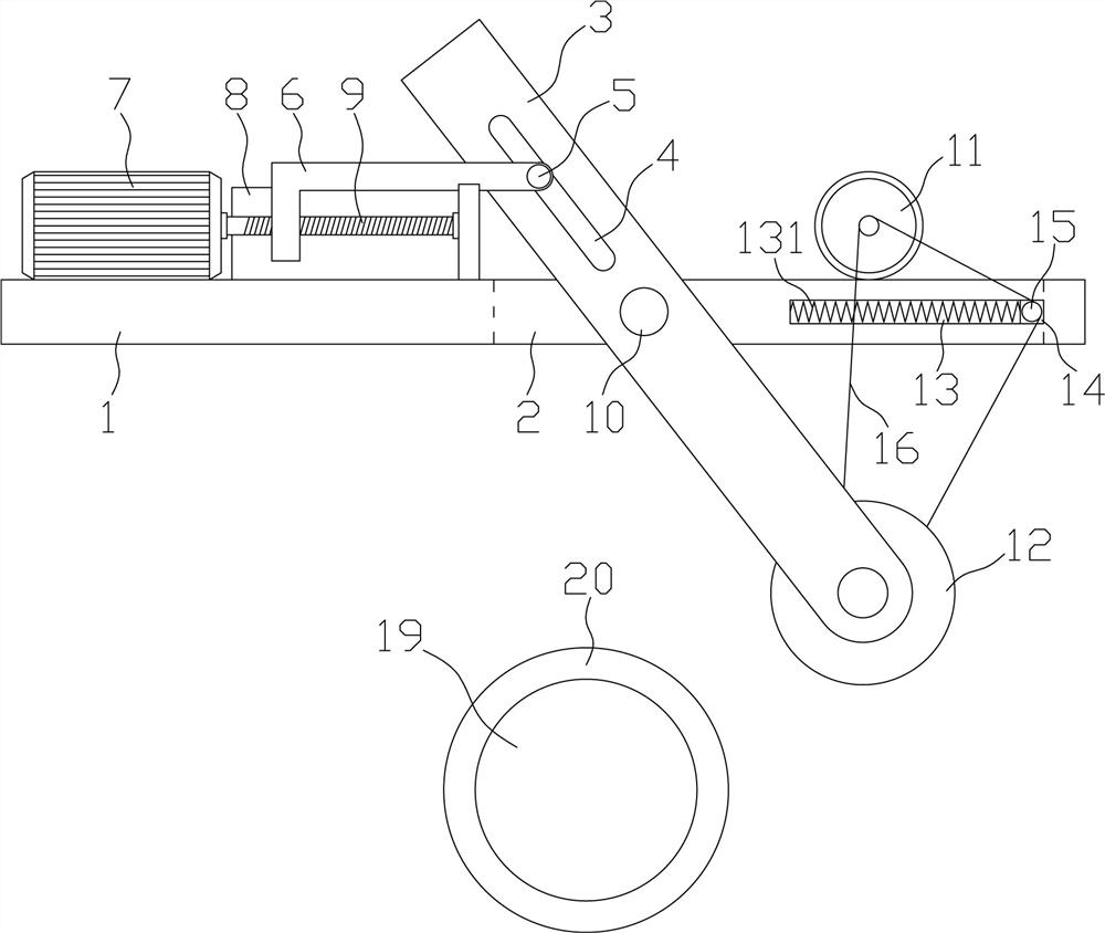
[0035] Such as Figure 2-4 Among them, an apron grinding device used on float glass conveying rollers, including a movable base plate 1, a slot 2 is provided on both sides of the movable base plate 1, and a support rod 3 is pierced in the slot 2 One end of the support rod 3 is provided with a grinding wheel 12, and the part of the support rod 3 far away from the end where the grinding wheel 12 is located is provided with a bar-shaped hole 4, and a horizontal bar 5 is pierced in the bar-shaped hole 4, and the horizontal bar 5 is fixedly arranged on One end of the horizontal section of the "L" shaped push rod 6;
[0036] The movable substrate 1 at one end of the slot 2 is provided with a first motor 7, the motor shaft of the first motor 7 is arranged horizontally and the motor shaft is connected with a threaded rod 9, and the threaded rod 9 passes through the "L" shaped ejector rod The vertical part of 6 is provided with and is threadedly connected between the vertical part of ...
Embodiment 2
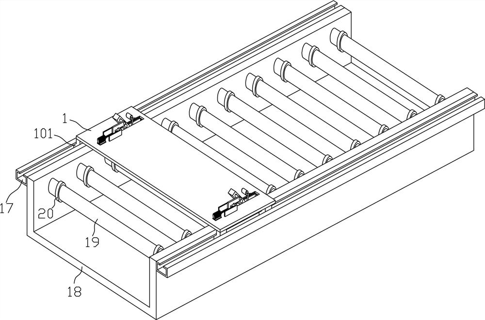
[0044] Such as figure 1 Among them, on the basis of Embodiment 1, the movable substrate 1 is arranged across the top of the conveyor 18, the bottom surfaces of both sides of the movable substrate 1 are provided with sliding seats 101, and the driving mechanism is arranged on the sliding seats 101, and the two sides of the conveyor 18 There is a track 17 on the side, and the sliding seat 101 is arranged in the track 17;
[0045] The strip hole 4, the horizontal rod 5, the "L" shaped ejector rod 6, the first motor 7, and the threaded rod 9 are all arranged above the movable substrate 1, and the grinding wheel 12 is arranged below the movable substrate 1.
Embodiment 3
[0047] Such as Figure 5 Among them, on the basis of Embodiment 1, the movable substrate 1 is arranged below the conveying roller 19 on the conveyor 18, and the inner wall of the conveyor 18 below the conveying roller 19 is provided with a horizontal groove 181, and the movable substrate 1 is provided on both sides. In the horizontal groove 181, drive mechanisms are arranged on both sides of the movable substrate 1 in the horizontal groove 181;
[0048] The shaped holes 4, horizontal rods 5, "L" shaped ejector rods 6, first motor 7 and threaded rods 9 are all arranged below the movable base plate 1, and the grinding wheel 12 is arranged above the movable base plate 1.
PUM
 Abstract
Description
Claims
Application Information
 - R&D Engineer
- R&D Manager
- IP Professional
- Industry Leading Data Capabilities
- Powerful AI technology
- Patent DNA Extraction
Browse by: Latest US Patents, China's latest patents, Technical Efficacy Thesaurus, Application Domain, Technology Topic.
© 2024 PatSnap. All rights reserved.Legal|Privacy policy|Modern Slavery Act Transparency Statement|Sitemap