Disinfection cloth cutting machine and cutting mechanism thereof
A cutting and cutting tool technology, which is used in metal sawing equipment, sending objects, tool dressing of sawing machine devices, etc. The effect of improving the safety rate
- Summary
- Abstract
- Description
- Claims
- Application Information
AI Technical Summary
Problems solved by technology
Method used
Image
Examples
Embodiment 1
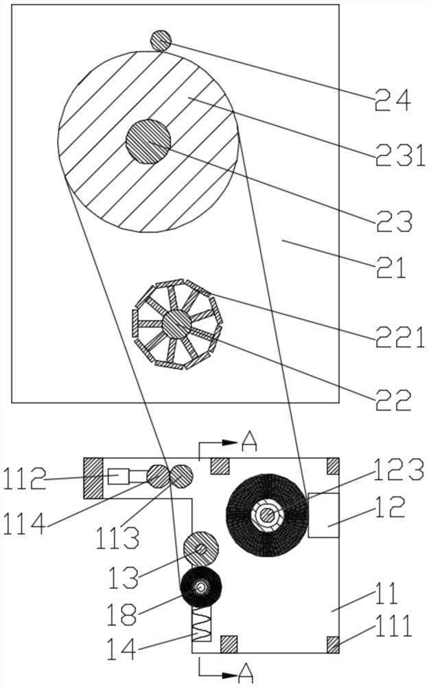
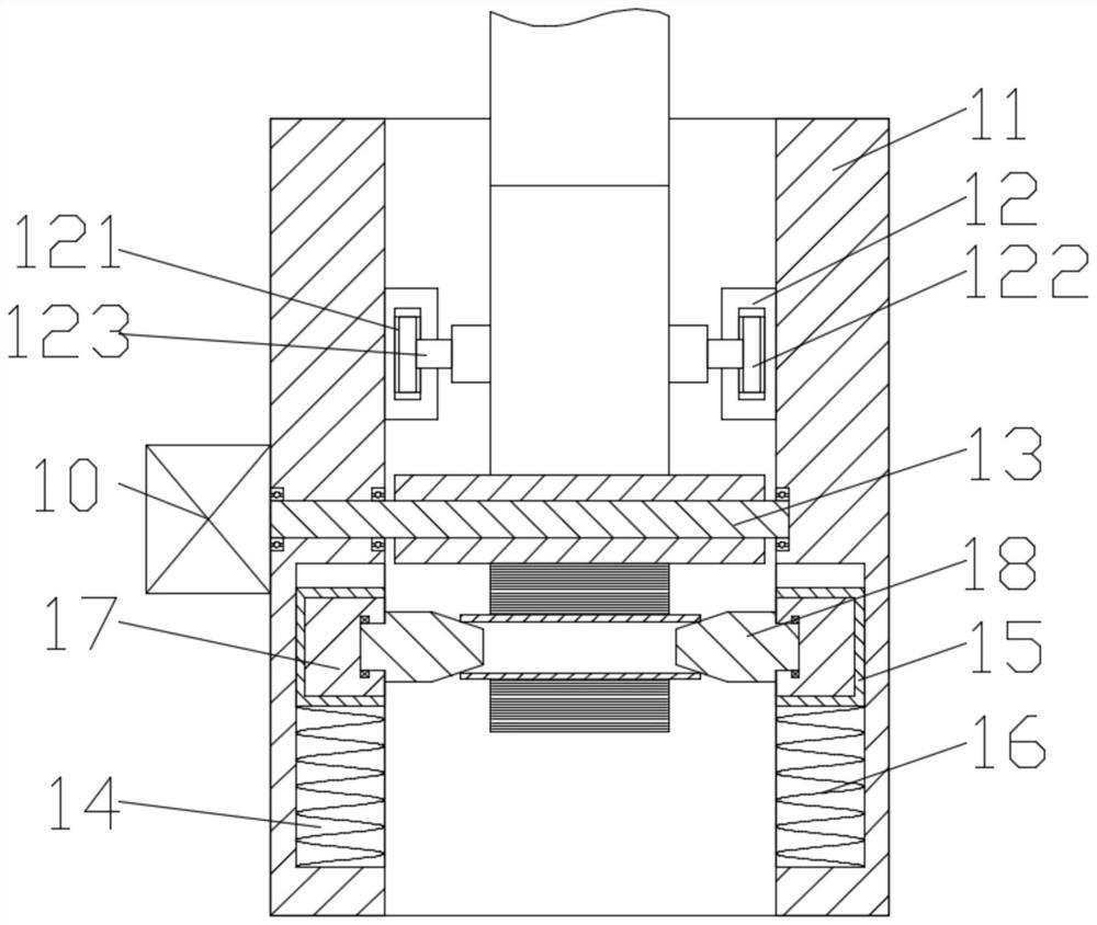
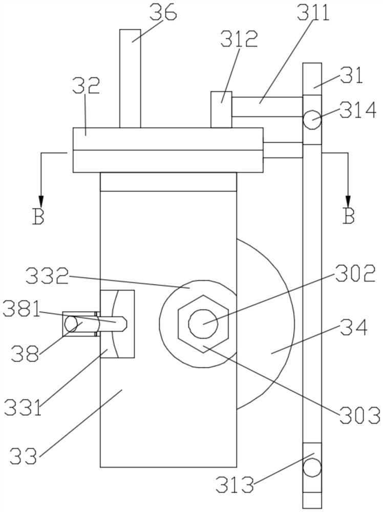
[0030] like Figure 1-5 as shown,
[0031] The leveling mechanism includes a pair of mutually symmetrical leveling fixing plates 21, a first leveling shaft 23 and a second leveling shaft 24 are rotated between the leveling fixing plates 21, and a leveling roller is fixed on the first leveling shaft 23 231, the smoothing roller 231 is close to the second smoothing shaft 24;
[0032] The sub-volume mechanism includes a pair of mutually symmetrical sub-volume fixing plates 11, and a plurality of supporting plates 111 are fixedly connected between the sub-volume fixing plates 11;
[0033] It includes two sub-volume cylinders 12, and the sub-volume cylinders 12 are respectively fixed on the sides of the sub-volume fixing plate 11 close to each other. The extension ends of the sub-volume cylinders 12 are provided with support grooves 121, and the support grooves Supporting bearings 122 are supported in 121, and the supporting bearings 122 are connected by split shafts 123, and the...
Embodiment 2
[0049] like Image 6 and Figure 7 As shown, the difference between Embodiment 2 and Embodiment 1 is that: a pair of swing plates 27 are symmetrically fixed on the first leveling shaft 22, and the leveling rollers 231 are located between the swing plates 27; A baffle shaft 271 is fixed between the fixed plates 21, and the baffle shaft 271 is used to support the swing plate 27. One of the smooth fixed plates 21 is fixedly connected with a swing motor 20, and the smoothing roller 231 is rotatably arranged on the on the first smoothing roller 23 .
[0050] The difference from the method used in Embodiment 1 is that the swing motor 10 drives the first leveling shaft 23 to rotate, the first leveling shaft 23 drives the swing plate 27 to swing, and the swing plate 27 drives the cutting Shaft 22 swings, and the cutting shaft 22 drives the cutting limiting shaft 221 to swing. When the cutting limiting shaft 211 swings to a suitable position, the saw blade 34 is used to carry out cut...
Embodiment 3
[0052] like Figure 8 and Figure 9 As shown, the difference between Embodiment 3 and Embodiment 1 is that: a guide slide plate 25 is fixed between the flat fixing plates 21, and a slide guide groove 26 is provided on the side of the guide slide plate 25 close to the cutting shaft 22 , the sliding guide plate 22 is provided with a through groove, the through groove communicates with the sliding guide groove 26, the connecting plate 32 is fixedly provided with a slider 37, and the sliding block 37 can be connected with the sliding guiding groove 26, the slider 37 can pass through the through groove and enter the guide groove.
[0053] The difference from the method used in Embodiment 1 is: put the slider 37 into the guide chute 26 through the through groove, push the handle 36 to drive the saw blade 34 along the gap between the cutting limit axis 221 For cutting, the slider 37 slides along the slide guide groove 26 .
PUM
 Abstract
Description
Claims
Application Information
 - R&D
- Intellectual Property
- Life Sciences
- Materials
- Tech Scout
- Unparalleled Data Quality
- Higher Quality Content
- 60% Fewer Hallucinations
Browse by: Latest US Patents, China's latest patents, Technical Efficacy Thesaurus, Application Domain, Technology Topic, Popular Technical Reports.
© 2025 PatSnap. All rights reserved.Legal|Privacy policy|Modern Slavery Act Transparency Statement|Sitemap|About US| Contact US: help@patsnap.com


