Switching method and switching system for steel wire rope in automobile crash test traction equipment

A technology of crash test and traction equipment, applied in the field of automobile crash test, can solve the problems of low breaking strength, easy detachment of new ropes when placed, shortening the life of steel wire ropes, etc.

Active Publication Date: 2021-04-09
CHINA AUTOMOTIVE TECH & RES CENT +2
View PDF7 Cites 1 Cited by
  • Summary
  • Abstract
  • Description
  • Claims
  • Application Information

AI Technical Summary

Problems solved by technology

During the use of the equipment, as the steel wire rope contacts the support rollers and steel beams, etc., the phenomenon of aging, strand pulling, and wire breakage occurs in the steel wire rope, which seriously shortens the life of the steel wire rope, and the material loss is very large. After the wire rope is inserted, its The joint is the weakest link in the whole wire rope, and its breaking strength is lower than that of the steel wire rope before the joint, and if the quality of the joint is low, the breaking strength of the joint of the steel wire rope will become lower than that of the normal steel wire rope
Since the diameter of the wire rope at the joint will increase, the unevenness of the rope surface will cause uneven force on each strand, resulting in abnormal wear and tear of the joint part, resulting in early broken wires
It has been observed that there are far more broken wires in the plugging part than in other parts, and this part of the outer steel wire is not wear-resistant, which will cause the diameter to become thinner and the wire rope to be scrapped, so it is necessary to replace it regularly and ensure the quality of the plugging part.
[0003]At present, the replacement of the old steel wire rope needs to face a large area of ​​dismantling of its surface covering mechanism, the old rope is not easy to take out, the old rope taken out in its entirety is not easy to place and recycle, and the new rope is easy to detach At the same time, the current wire rope insertion method also has the problems of high cost, long time consumption, and inability to guarantee the quality and radius of the insertion point. As the wire rope is an important part of the traction mechanism, the quality of the wire rope insertion will vary. Directly affect the operation safety of equipment and personal safety of personnel

Method used


Image

  • Switching method and switching system for steel wire rope in automobile crash test traction equipment
  • Switching method and switching system for steel wire rope in automobile crash test traction equipment
  • Switching method and switching system for steel wire rope in automobile crash test traction equipment

Examples


Embodiment 1

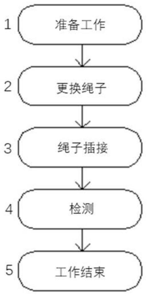
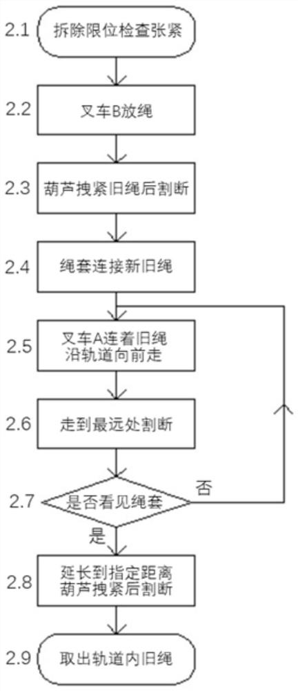
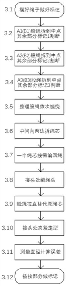
[0079] A method for switching steel wire ropes in traction equipment for automobile crash tests, such as figure 1 As shown, it includes changing the rope, rope insertion and detection in turn, wherein changing the rope includes the following steps (such as figure 2 shown):

[0080] (1) Prepare the new steel wire rope (the specifications of the steel wire rope required by the automobile crash test equipment are generally 16mm in diameter, 6 strands of metal wire strand core, large strands are twisted to the right, and small strands are twisted to the left), and ensure that the length is long enough (if it needs to be replaced) If the wire rope length is 600 meters, you need at least 650-700 meters in length).

[0081] (2) Remove the electronic limit device of the heavy hammer of the steel wire rope. The function of the heavy hammer is to ensure that the long steel wire rope will not jump out of the underground track during operation. Therefore, it is convenient to remove this...

Embodiment 2

[0109] Such as Figure 5 As shown, this embodiment provides a steel wire rope switching system in the traction equipment for automobile crash test, including: a fixing device, a moving device, a new steel wire rope 3 and a truncated old steel wire rope 4, and the truncated old steel wire rope 4 is arranged underground In the track, the truncated old wire rope 4 includes a front end and a rear end (not shown);

[0110] The mobile device and the fixed device are parked on the ground along the direction of the underground track, the mobile device is parked before the fixed device, a new steel wire rope is installed on the fixed device, the free end of the new steel wire rope 3 is connected to the front end, and the mobile device is connected to the fixed device. connected to the back end.

[0111] The fixing device is a forklift A1, and the moving device is a forklift B2;

[0112] The free end of the new steel wire rope 3 and the outer side of the front end are provided with a ...


PUM


Abstract

The invention relates to a switching method and a switching system for steel wire rope in automobile crash test traction equipment; the switching method comprises the steps: cutting off an old steel wire rope at an initial position, enabling the rear end of the cut-off old steel wire rope to be connected with a moving device, and enabling the front end to be connected with the free end of a new steel wire rope; driving, by the moving device, the rear end to move towards the end point of the underground rail, meanwhile, driving, by the front end, the new steel wire rope to enter the underground rail, when the moving device moves to the end point of the underground rail, cutting off the old steel wire rope again at the initial position to obtain a cut-off part and the rear end, and returning the moving device to the initial position and connects the rear end to the moving device; repeating the steps until the front end is taken out of the underground rail, completely cutting off the old steel wire rope, cutting off the new steel wire rope, and then inserting the two ends of the new steel wire rope together. The method adopts the mode that the old steel wire rope drives the new steel wire rope to enter the rail, finally completes change-over, can ensure that the new steel wire rope completely enters the rail without errors, and is convenient and accurate to change and low in cost.

Description

technical field [0001] The invention relates to the field of automobile collision tests, in particular to a method and system for switching wire ropes in traction equipment for automobile collision tests. Background technique [0002] Automobile crash test is a necessary test in the study of automobile passive safety. It simulates and reproduces the forms of collision accidents that may occur in daily life, and analyzes the movement status and damage of the occupants and the vehicle before and after the vehicle collision. In the early stage, more effective modification suggestions were provided, and more intuitive reference data were provided for consumers during the purchase process. In the entire automobile crash test equipment, the traction system is an integral part of the entire test equipment. It meets the test requirements by giving different expected speeds to the test vehicle and the target vehicle through the steel wire rope. Base. The steel wire rope is a spiral...

Claims


Application Information

Patent Timeline
Patent Type & Authority Applications(China)
IPC IPC(8): G01M17/007D07B7/16
CPCG01M17/0078D07B7/169
Inventor 陈弘鞠帆刘志新马伟杰肖广宇刘汉渝刘伟东
Owner CHINA AUTOMOTIVE TECH & RES CENT
Why Eureka
Try Eureka