Gastrointestinal fluid decompression device for gastrointestinal surgery

A decompression device, gastrointestinal fluid technology, applied in the direction of balloon catheters, catheters, medical equipment, etc., can solve the problems of mucous membrane inner wall vibration, shock, nozzle insertion into effusion, etc., and achieve the effect of cost saving

Pending Publication Date: 2021-04-13
THE SECOND AFFILIATED HOSPITAL OF ANHUI MEDICAL UNIV
View PDF0 Cites 1 Cited by
  • Summary
  • Abstract
  • Description
  • Claims
  • Application Information

AI Technical Summary

Problems solved by technology

[0003] The principle of the commonly used gastrointestinal decompressor at present is to suck out the effusion in the patient's abdominal cavity through negative pressure suction, and the negative pressure work can be realized by siphon structure, piston extraction structure, etc. When extracting liquid under negative pressure, even if the patient is in a sitting or inclined position, the nozzle of the gastric tube may not

Method used


Image

  • Gastrointestinal fluid decompression device for gastrointestinal surgery
  • Gastrointestinal fluid decompression device for gastrointestinal surgery
  • Gastrointestinal fluid decompression device for gastrointestinal surgery

Examples


Embodiment 1

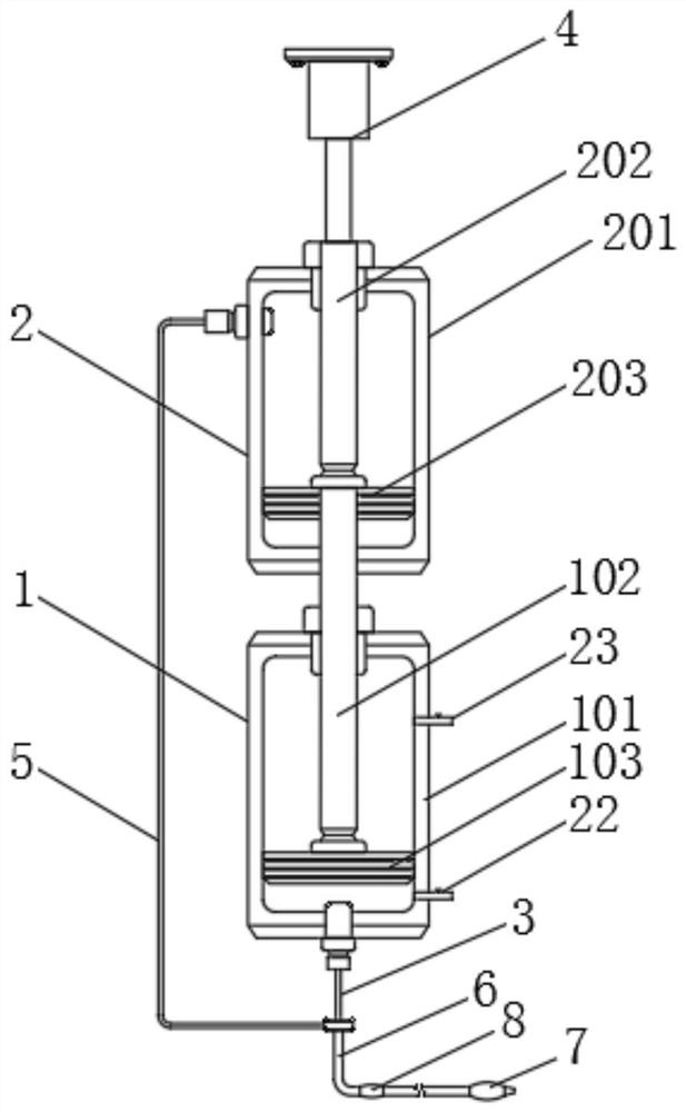
[0032] Such as Figure 1-4 As shown, a gastrointestinal fluid decompression device for gastrointestinal surgery includes a suction device 1, an inflation device 2, a suction tube 3, a lifting mechanism 4, an inflation tube 5, a double-lumen tube 6 and an inflatable balloon 7;

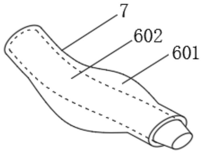
[0033] The liquid pumping device 1 communicates with the inner chamber 602 of the double-cavity tube 6 through the liquid pumping tube 3, and the lifting mechanism 4 drives the liquid pumping device 1 to extract the effusion;

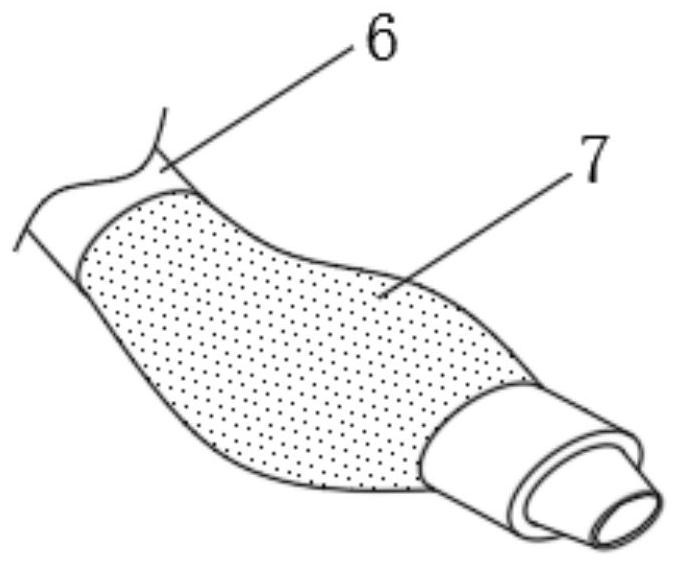
[0034] The inflatable device 2 communicates with the outer chamber 601 of the double-lumen tube 6 through the inflatable tube 5, the inflatable air bag 7 is arranged at the extraction end of the double-lumen tube 6 and communicates with the outer cavity 601, and the lifting mechanism 4 simultaneously drives the inflatable device 2. Supply air to the inflatable airbag 7, and the inflatable airbag 7 will bulge to fill the intraperitoneal space occupied by the removed effusion.

[...

Embodiment 2

[0051] Such as Figure 7 As shown, the inflator 2 and the pumping device 1 are arranged side by side, and the lifting mechanism 4 is arranged between the charging device 2 and the pumping device 1. The lifting mechanism 4 includes a screw 401, a screw slide 402 and Servo motor 403, the top of the screw rod 401 is driven by the servo motor 403, the screw rod slider 402 is screwed to the outside of the screw rod 401, and the two ends of the screw rod slider 402 pass through the cross bar and the pumping connecting rod 102 and the inflation connecting rod 202 Fixedly connected, the liquid suction pipe 3 is fixedly arranged at the bottom of the liquid suction tank 101, the inflation pipe 5 is fixedly arranged at the top of the inflation pipe 5, and the liquid suction piston 103 is in the position of the liquid suction tank 101 and the inflation piston 203 is inflated. The position in the tank 201 is the same, and the size and shape of the pumping tank 101 and the inflation tank 20...


PUM


Abstract

The invention relates to a gastrointestinal fluid decompression device for gastrointestinal surgery. The gastrointestinal fluid decompression device comprises a fluid pumping device, an inflation device, a fluid pumping pipe, a lifting mechanism, an inflation pipe, a double-cavity pipe and an inflation air bag, wherein the fluid pumping device communicates with an inner cavity of the double-cavity pipe through the fluid pumping pipe, and the lifting mechanism drives the fluid pumping device to pump accumulated fluid; and the inflation device communicates with an outer cavity of the double-cavity pipe through the inflation pipe, the inflation air bag is arranged at the pumping end of the double-cavity pipe and communicates with the outer cavity, the lifting mechanism drives the inflation device to supply air to the inflation air bag at the same time, and the inflation air bag bulges to fill abdominal cavity space occupied by extracted hydrops. The lifting mechanism is used for simultaneously driving the fluid pumping device and the inflation device, the inflation air bag is inflated while effusion is pumped, it can be guaranteed that a pipe opening corresponding to the inner cavity is completely inserted into effusion, and the situation that the pipe opening is not completely inserted into the effusion, so that the inner wall of the mucous membrane vibrates, and a patient feels uncomfortable, is avoided.

Description

technical field [0001] The invention belongs to the technical field of medical equipment, and in particular relates to a gastrointestinal fluid decompression device for gastrointestinal surgery. Background technique [0002] In the clinical treatment of gastrointestinal surgery, when the patient has intraperitoneal fluid or increased intraperitoneal pressure, it is necessary to use a gastrointestinal decompressor to drain the gastrointestinal fluid. [0003] The principle of the commonly used gastrointestinal decompressor at present is to suck out the effusion in the patient's abdominal cavity through negative pressure suction, and the negative pressure work can be realized by siphon structure, piston extraction structure, etc. When extracting liquid under negative pressure, even if the patient is in a sitting or inclined position, the nozzle of the gastric tube may not be completely inserted into the liquid. Once the nozzle is half in the liquid or not in the liquid at all,...

Claims


Application Information

Patent Timeline
IPC IPC(8): A61M1/00A61M25/10
CPCA61M25/1011A61M2205/3331A61M2205/3379A61M2205/3653A61M2209/08A61M2209/10A61M2210/1042A61M25/10181A61M25/10184A61M2210/005
Inventor 刘志宁
Owner THE SECOND AFFILIATED HOSPITAL OF ANHUI MEDICAL UNIV
Why Eureka
Try Eureka