Automobile radiator and production process thereof

A technology of automobile radiator and heat pipe, which is applied in the direction of heat exchanger shell, heat transfer modification, heat exchange equipment, etc. The effect of moving speed and ensuring constant water pressure

Pending Publication Date: 2021-04-13
黄山杰尔马热交换系统有限公司
View PDF0 Cites 0 Cited by
  • Summary
  • Abstract
  • Description
  • Claims
  • Application Information

AI Technical Summary

Problems solved by technology

[0003] However, because the existing automobile radiators dissipate heat through multiple pipes in contact with the air during use, and the water flow inside the pipes can only dissipate heat at the parts in contact with the pipes, resulting in poor heat dissipation and difficult to meet the heat dissipation requirements of the vehicle.

Method used


Image

  • Automobile radiator and production process thereof
  • Automobile radiator and production process thereof
  • Automobile radiator and production process thereof

Examples


Embodiment 1

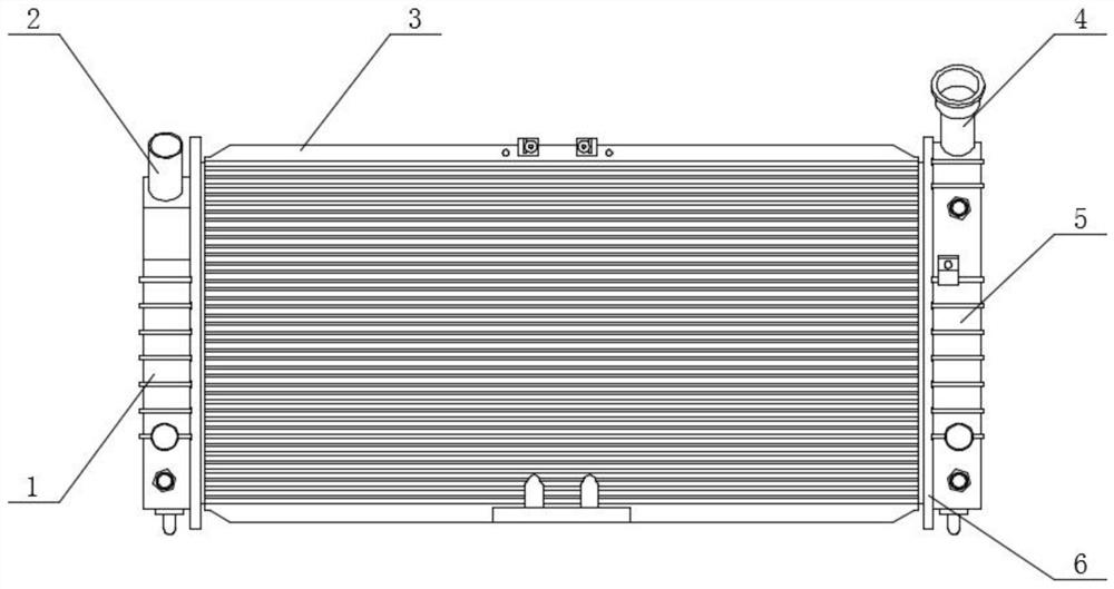
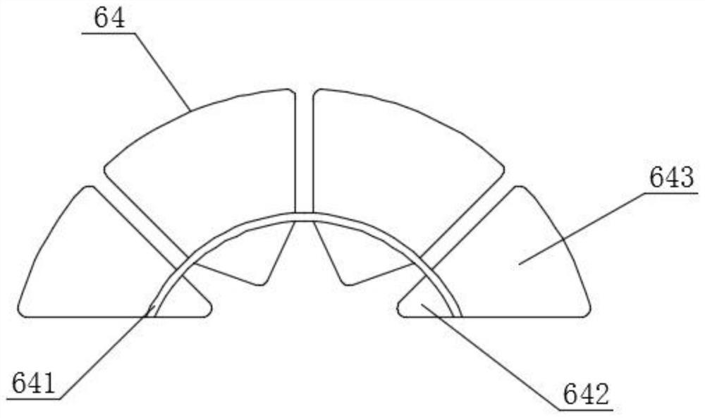
[0028] Such as Figure 1-3 As shown, a kind of automobile radiator comprises water outlet pipe 2, and the lower end of water outlet pipe 2 is fixed with water outlet box 1, and the right end of water outlet box 1 is clamped with heat dissipation pipe 6, and the front end of heat dissipation pipe 6 is fixed with heat dissipation device 3, heat dissipation pipe The right end of 6 is clamped with a water inlet tank 5, and the upper end of the water inlet tank 5 is fixed with a water inlet pipe 4, and the cooling pipe 6 includes a fixed frame 61, and a connecting column 62 is fixed in the middle of the fixed frame 61, and the bottom of the connecting column 62 is on the fixed frame. The middle position of 61 is fixed with connecting pipe 63, and the surface of connecting pipe 63 is welded and fixed with radiating fin 64, and the middle of radiating fin 64 is provided with guiding device 65, and radiating fin 64 comprises radiating fin 643, and the lower end of radiating fin 643 A ...

Embodiment 2

[0031] Such as Figure 1-4 As shown, a kind of automobile radiator comprises water outlet pipe 2, and the lower end of water outlet pipe 2 is fixed with water outlet box 1, and the right end of water outlet box 1 is clamped with heat dissipation pipe 6, and the front end of heat dissipation pipe 6 is fixed with heat dissipation device 3, heat dissipation pipe The right end of 6 is clamped with a water inlet tank 5, and the upper end of the water inlet tank 5 is fixed with a water inlet pipe 4, and the cooling pipe 6 includes a fixed frame 61, and a connecting column 62 is fixed in the middle of the fixed frame 61, and the bottom of the connecting column 62 is on the fixed frame. The middle position of 61 is fixed with connecting pipe 63, and the surface of connecting pipe 63 is welded and fixed with cooling fin 64, and the middle of cooling fin 64 is provided with guiding device 65, and guiding device 65 comprises fixing plate 651, and the front end of fixing plate 651 is welde...

Embodiment 3

[0034] Such as Figure 1-5 As shown, a kind of automobile radiator comprises water outlet pipe 2, and the lower end of water outlet pipe 2 is fixed with water outlet box 1, and the right end of water outlet box 1 is clamped with heat dissipation pipe 6, and the front end of heat dissipation pipe 6 is fixed with heat dissipation device 3, heat dissipation pipe The right end of 6 is clamped with water inlet box 5, and the upper end of water inlet box 5 is fixed with water inlet pipe 4, and water inlet pipe 4 comprises pipe body 41, and the inner surface of pipe body 41 is fixed with dividing plate 42.

[0035] The water inlet pipe 4 introduces the water flow with high external temperature. The water flow moves along the pipe body 41 and is divided into three water flows separated by the partition plate 42. The three flows enter the three chambers inside the water inlet tank 5 along the pipe, thereby entering Inside the three connecting pipes 63, the water flow can be evenly divi...


PUM


Abstract

The invention provides an automobile radiator. The radiator comprises a water outlet pipe, wherein a water outlet tank is fixed to the lower end of the water outlet pipe, a heat radiating pipe is clamped to the right end of the water outlet tank, a heat radiating device is fixed to the front end of the heat radiating pipe, a water inlet tank is clamped to the right end of the heat radiating pipe, and a water inlet pipe is fixed to the upper end of the water inlet tank. According to the radiator, a fixed ring is fixed to the surface of a connecting pipe, a heat-conducting fin is inserted into the connecting pipe and directly makes contact with hot water inside the connecting pipe, a temperature of the surface of the hot water can be directly transmitted to the surface of the heat-conducting fin, water flow in the center of the connecting pipe can guide heat out through the heat-conducting fin, and meanwhile a contact area between a heat radiating fin and air is increased, the heat radiating efficiency is improved, so that a temperature of an engine is controlled within a proper range.

Description

technical field [0001] The invention relates to the field of automobile industry, in particular to an automobile radiator and a production process thereof. Background technique [0002] The car radiator is composed of three parts: the water inlet chamber, the water outlet chamber and the radiator core. The coolant flows in the radiator core, and the air passes outside the radiator. The hot coolant cools by dissipating heat to the air, and the cold air heats up by absorbing heat from the coolant. [0003] However, because the existing automobile radiators are in use through multiple pipes in contact with the air to dissipate heat, and the water flow inside the pipes can only dissipate heat at the parts in contact with the pipes, resulting in poor heat dissipation and difficult to meet the heat dissipation requirements of the vehicle. Contents of the invention [0004] The object of the present invention is to provide an automobile radiator and its production process to sol...

Claims


Application Information

Patent Timeline
Patent Type & Authority Applications(China)
IPC IPC(8): F01P11/00F28F1/42F28F13/06F28F13/02F28F9/22B23P15/26
CPCB23P15/26F01P11/00F28F1/422F28F9/22F28F13/02F28F13/06F28F2001/428F28F2009/222
Inventor 杨骏曹定王健伟
Owner 黄山杰尔马热交换系统有限公司
Why Eureka
Try Eureka