
Double-shaft planetary rotary spray head for cleaning equipment

A technology of cleaning equipment and planetary rotation, applied in mechanical equipment, cleaning methods and appliances, spraying devices, etc., can solve the problems of fast rotation speed of nozzles, reduce production efficiency, consume large working time and energy, etc., and achieve dense and uniform paths. The effect of cleaning, saving working time and energy consumption

Pending Publication Date: 2021-04-13
上海弦力清洗设备有限公司
View PDF0 Cites 0 Cited by
  • Summary
  • Abstract
  • Description
  • Claims
  • Application Information

AI Technical Summary

Problems solved by technology

[0003] During the rotation process of the existing high-pressure rotary nozzle, the power is generated by the rotation of the turbine blades driven by water pressure, and the rotation speed of the nozzle cannot be controlled. When cleaning the equipment, the nozzle rotation speed will be too fast to remove the dirt on the equipment. , even if the motion cycle is lengthened, the dirt on the equipment cannot be removed, and the ideal cleaning effect cannot be achieved. The rotation speed of the nozzle is too slow, which consumes a lot of working time of the operator, reduces production efficiency, and consumes too much energy.
[0004] The existing high-pressure rotary nozzles cannot accurately control the characteristic curves between the rotation speed of the nozzle and the striking force of the nozzle, and between the striking force of the nozzle and the spraying distance, which can only be obtained through experiments, resulting in a series of problems such as difficulty in model selection
[0005] In the existing high-pressure rotary nozzle, the main shaft and the planetary shaft rotate in the same direction, resulting in uneven impact force on the sprayed coverage surface of the high-pressure rotary nozzle. When cleaning the equipment, repeated work due to uneven cleaning consumes a lot of working time and energy

Method used


Image

  • Double-shaft planetary rotary spray head for cleaning equipment
  • Double-shaft planetary rotary spray head for cleaning equipment

Examples


Embodiment Construction

[0019] The following will clearly and completely describe the technical solutions in the embodiments of the present invention with reference to the accompanying drawings in the embodiments of the present invention. Obviously, the described embodiments are only some, not all, embodiments of the present invention.

[0020] Examples of the described embodiments are shown in the drawings, wherein like or similar reference numerals designate like or similar elements or elements having the same or similar functions throughout. The embodiments described below by referring to the figures are exemplary and are intended to explain the present invention and should not be construed as limiting the present invention.

[0021] In describing the present invention, it should be understood that the terms "center", "longitudinal", "transverse", "length", "width", "thickness", "upper", "lower", "front", " Back", "Left", "Right", "Vertical", "Horizontal", "Top", "Bottom", "Inner", "Outer", "Clock...


PUM


Abstract

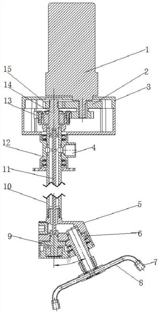
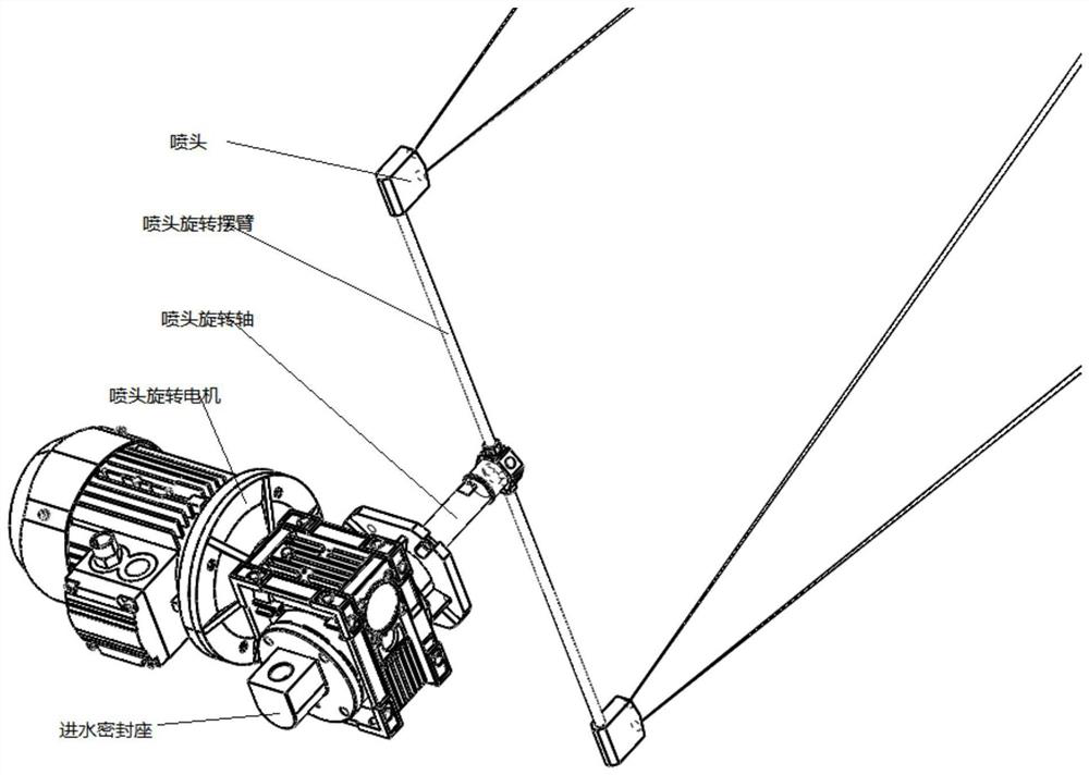
The invention relates to the technical field of high-pressure rotary cleaning equipment, and discloses a double-shaft planetary rotary spray head for cleaning equipment. The double-shaft planetary rotary spray head comprises a motor, a double gear, a gear box, a water inlet, a planetary gear rotary bearing seat, a planetary gear, nozzles, a nozzle swing arm, a main shaft gear, a water passing rod, a hexagonal transmission shaft, a water inlet sealing seat, a second gear, a main shaft gear driving shaft and a first gear. According to the double-shaft planetary rotary spray head, power of the double-shaft planetary high-pressure rotary spray head is provided by the motor, the gears and the transmission shaft are adopted for transmission, the rotating speed of the spray head can be accurately controlled, and in addition, the multiple sets of gears are used for controlling the transmission direction, so that the rotating directions and the rotating speeds of the main shaft gear and the planetary gear rotary bearing seat are different, and relative to an original high-pressure rotary nozzle, a path left by water jet on the cleaning surface are denser and more uniform, cleaning is cleaner, and the working time and energy consumption are saved.

Description

technical field [0001] The invention relates to the technical field of high-pressure rotary cleaning equipment, in particular to a dual-axis planetary rotary spray head for cleaning equipment. Background technique [0002] Existing high-pressure rotary nozzles mainly include water inlet, water inlet pipe fittings, turbine, gear fixing rod, gear, nozzle rotation fixing shaft, shaft cavity, nozzles (2, 3...n), sealing plate, etc. components, which form a high-pressure cleaning assembly whose nozzle can rotate automatically. The turbine blades are driven to rotate by water pressure, which is transmitted to the reduction gear, and the nozzle is driven to rotate on the fixed shaft to make the nozzle rotate automatically. figure 2 shown. [0003] During the rotation process of the existing high-pressure rotary nozzle, the power is generated by the rotation of the turbine blades driven by water pressure, and the rotation speed of the nozzle cannot be controlled. When cleaning the ...

Claims


Application Information

Patent Timeline
Patent Type & Authority Applications(China)
IPC IPC(8): F16H1/28B08B3/02B05B3/02
CPCB05B3/02B08B3/02F16H1/2854
Inventor 陈思亮陈彬高志伟席凯
Owner 上海弦力清洗设备有限公司
Learn More