Anti-reflection laser

A laser and light-returning technology, applied in the field of lasers, can solve the problems of laser equipment hazards and failures that cannot be completely solved, and achieve the effects of reducing light absorption power, improving working life, and avoiding burnout

Active Publication Date: 2021-08-27
SHANGHAI FEIBO LASER TECH CO LTD
View PDF7 Cites 0 Cited by
  • Summary
  • Abstract
  • Description
  • Claims
  • Application Information

AI Technical Summary

Problems solved by technology

Although, when the return light of the laser is reversely transmitted along the anti-return fiber to the pigtail of the laser, most of the light in the fiber core will be coupled into the pigtail cladding, and then leak out through the roughened section of the pigtail cladding , unable to continue reverse transmission into the laser, it can effectively prevent the return light from entering the laser, but often the return light has not yet entered the laser, and it will cause its failure when it is returned in the output optical cable, which cannot completely solve the problem of the return light on the entire laser equipment Hazard problem

Method used


Image

  • Anti-reflection laser
  • Anti-reflection laser
  • Anti-reflection laser

Examples


Embodiment Construction

[0023] The present invention will be further described below in conjunction with the embodiments and accompanying drawings, but the protection scope of the present invention should not be limited thereby.

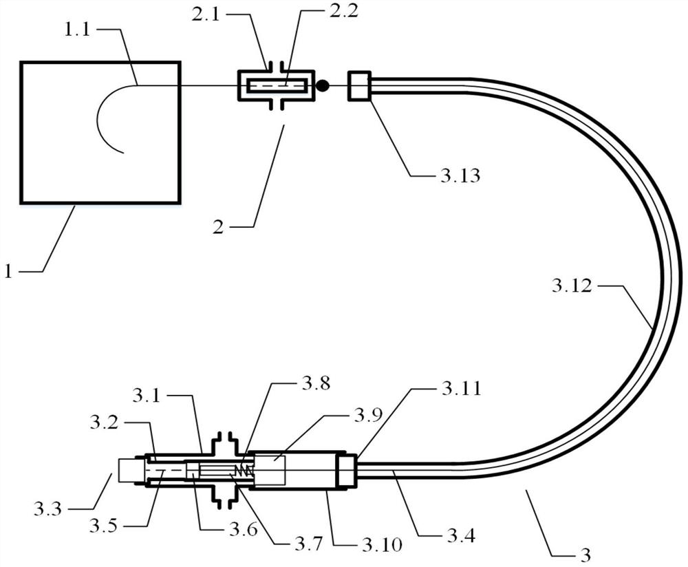
[0024] see first figure 1 , figure 1 It is a structural schematic diagram of the anti-reflection laser of the present invention. It can be seen from the figure that the anti-reflection laser of the present invention includes a laser output module 1, a cladding filter module 2 and an output optical cable 3. The laser output module 1 includes an output The optical fiber 1.1, the cladding filter module 2 includes a water-cooled housing 2.1, the first fiber texturing area 2.2, and the output optical cable 3 includes an output head main body 3.1, an inner core 3.2, a quartz column 3.3, and an output optical cable optical fiber 3.4, the second optical fiber roughening area 3.5, reflective lens 3.6, quartz gasket 3.7, spring 3.8, optical fiber fixing part 3.9, outer sleeve 3.10, ...


PUM


Abstract

An anti-reflection laser includes a laser output module, the laser output by the laser output module is transmitted through the core of the output optical fiber, a section of the output optical fiber is stripped of the coating layer, and the surface of the second cladding is roughened, This section of output optical fiber is used as the first fiber roughening area to filter out the cladding light in the optical fiber, the end of the output optical fiber is fused with the output optical fiber of the output optical cable, and the end of the output optical fiber is fused with the quartz column, A section of the output optical fiber is stripped of the coating layer, and the surface of the third cladding is roughened, and this section of the output optical fiber is used as the second fiber roughening area to filter out the cladding light in the optical fiber. The output optical fiber is a double-clad optical fiber, and the output optical cable optical fiber is a triple-clad optical fiber. The invention can greatly reduce the safety risk brought by the returning light to the laser and improve the working life of the laser.

Description

technical field [0001] The invention relates to the technical field of lasers, in particular to an anti-return light laser. Background technique [0002] In the industrial processing of lasers, depending on the working material, there will be more or less laser light reflected from the surface of the material into the output optical cable of the laser, causing the failure of the device or even the whole machine. The existing technology of domestic lasers is to filter out the cladding fiber near the output end of the output optical cable, but due to the limited water cooling effect of the output optical cable, it can meet the effect of filtering the return light when the power of the return light is not large. However, when the processing object is a thick and highly reflective material, since the laser requires high-power operation, the power of the returning light will be very large in this case. If the original filtering process is still used, the water cooling of the outp...

Claims


Application Information

Patent Timeline
Patent Type & Authority Patents(China)
IPC IPC(8): H01S3/04H01S3/00H01S5/00H01S5/024
CPCH01S3/0064H01S3/0407H01S5/0064H01S5/02423H01S5/02438
Inventor 韦锦李文涛关珮雯马明凯
Owner SHANGHAI FEIBO LASER TECH CO LTD
Why Eureka
Try Eureka