Neodymium iron boron pressed blank isostatic pressing die body
An isostatic pressing and neodymium-iron-boron technology, applied in the direction of magnetic objects, magnetic materials, electrical components, etc., can solve the problems of slow heat transfer, inconvenient demoulding, etc., and achieve easy handling, improved molding effect, and rapid temperature rise Effect
- Summary
- Abstract
- Description
- Claims
- Application Information
AI Technical Summary
Problems solved by technology
Method used
Image
Examples
Embodiment 1
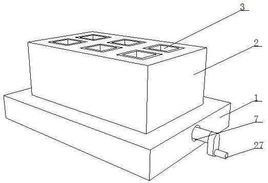
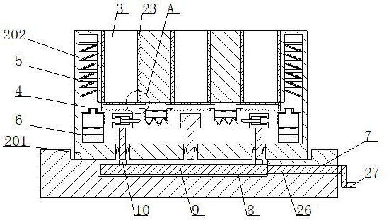
[0033] Such as figure 1 - Figure 7 As shown, the present invention provides a NdFeB compact isostatic die body, including a rectangular fixed seat 1, a die body structure 2, a placement groove 3, a working chamber 4, a heat transfer mechanism 5 and a boiling mechanism 6, The inner wall of the rectangular fixed seat 1 is movably connected with a mold body structure 2, the mold body structure 2 includes a base plate 201 and a mold body 202, the top of the base plate 201 is provided with a mold body 202, and the top of the mold body 202 is provided with a placement groove 3, and the mold body The bottom of 202 is provided with a working chamber 4, the top left and right ends of the inner wall of the working chamber 4 are provided with a heat transfer mechanism 5, and the left and right ends of the inner wall bottom of the working chamber 4 are provided with a boiling mechanism 6. Directly below the heat mechanism 5, a storage bag 19 is provided on the top of the inner wall of t...
Embodiment 2
[0035] Such as Figure 1-4Shown, on the basis of embodiment 1, the present invention provides a kind of technical scheme: boiling mechanism 6 comprises outer casing 601, acetone solution 602 and air vent 603, and the inner wall of outer casing 601 is provided with acetone solution 602, and outer casing 601 The right side is provided with a ventilation hole 603, the top of the outer shell 601 is provided with a cover 604, the right side of the rectangular fixed seat 1 is provided with a circular groove 7, and the right end of the circular groove 7 is provided with a movable groove 8, and the inner wall of the movable groove 8 A rotating roller 9 is movably connected, and the top of the rotating roller 9 is evenly provided with an impact block 10, and the surface of the bottom plate 201 is uniformly provided with a rectangular groove 11, and the left and right sides of the inner wall of the rectangular groove 11 are movably connected with a transmission rod 13 through the provide...
Embodiment 3
[0037] Such as Figure 1-7 As shown, on the basis of Embodiment 1 and Embodiment 2, the present invention provides a technical solution: the top and bottom of the sliding groove 15 are provided with a fixing groove 16, and the inner wall of the fixing groove 16 is movably connected with a spring 17 provided with Squeeze rod 18, the bottom of receiving bag 19 is provided with folding bag body 20, and the inner wall of receiving bag 19, folding bag body 20 is all provided with cooling liquid 21, and the top of left and right sides of receiving bag 19 is all provided with circulation tube 22, puts The inwall of putting groove 3 is provided with first rubber pad 23 around, and the inner wall bottom of putting groove 3 is provided with second rubber pad 24, and the side of second rubber pad 24 is provided with cavity 25, and the inwall of cavity 25 It is movably connected with the flow pipe 22, and the right end of the rotating roller 9 is provided with a control rod 26. The contro...
PUM
 Abstract
Description
Claims
Application Information
 - R&D
- Intellectual Property
- Life Sciences
- Materials
- Tech Scout
- Unparalleled Data Quality
- Higher Quality Content
- 60% Fewer Hallucinations
Browse by: Latest US Patents, China's latest patents, Technical Efficacy Thesaurus, Application Domain, Technology Topic, Popular Technical Reports.
© 2025 PatSnap. All rights reserved.Legal|Privacy policy|Modern Slavery Act Transparency Statement|Sitemap|About US| Contact US: help@patsnap.com


