Roller type textile printing device

A textile and printing technology, applied in the field of textile printing, can solve problems such as pollution and poor quality of printed products

Active Publication Date: 2021-04-16
芜湖升星纺织品有限公司
View PDF4 Cites 1 Cited by
  • Summary
  • Abstract
  • Description
  • Claims
  • Application Information

AI Technical Summary

Problems solved by technology

In traditional rotary screen printing, after the overall printing is completed, it is transported to a special steamer for steaming work. When printing in different rotary screens, the printing paste printed on the surface of the textile cannot quickly penetrate into the textile. A small amount of color paste accumulates on the surface of the textile, which makes the color paste move to the area to be printed and dyed under the action of gravity to cause pollution, and then makes the quality of the printed product of the entire textile poor

Method used


Image

  • Roller type textile printing device
  • Roller type textile printing device
  • Roller type textile printing device

Examples


Embodiment 1

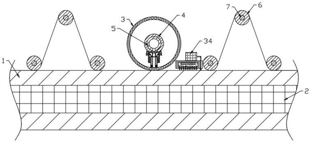
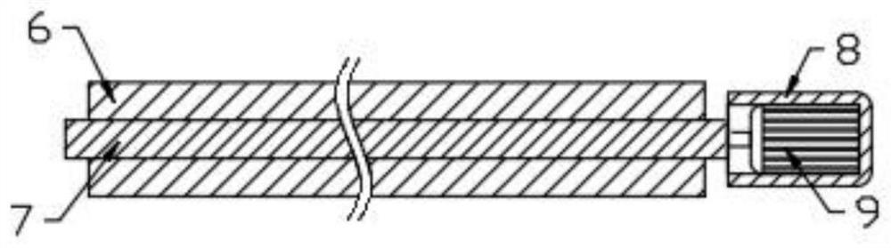
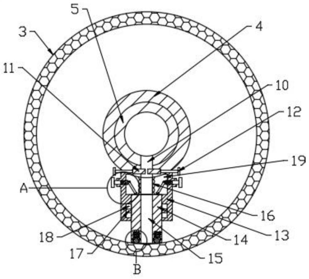
[0030] see Figure 1-10 , a roll-type textile printing device, comprising a workbench 1 and a magnetic table 2 arranged in the workbench 1, a frame body is arranged on the workbench 1, a number of dyeing rollers 3 are arranged on the workbench 1, and the dyeing rollers 3 A knife rest 4 and an infusion tube 5 are arranged inside, and a number of transportation components for transporting textiles are interlaced between several dyeing rollers 3. Through holes 10 are provided on the lower sides of the knife rest 4 and the infusion tube 5, and on the knife rest 4, there are There is a control assembly for controlling the content of color paste output from the through hole 10, a guide seat 13 is fixedly connected to the lower end of the knife holder 4, a scraper 14 is slidingly connected to the guide seat, an infusion channel 15 is provided in the scraper 14, and a cavity is provided in the guide seat 13 19. The cavity 19 is provided with a hose 16 communicating with the through ho...

Embodiment 2

[0049] Further improvements are made on the basis of Example 1, and the improvements are as follows: the pretreatment assembly includes a heating plate 37, a slurry suction cylinder 38, a second slurry suction head 39, a through cavity 40, a communication pipe 43 and a second negative pressure pump 44. A number of heating plates 37 are arranged on both sides of the dyeing roller 3 on the workbench 1, and a number of slurry suction cylinders 38 are symmetrically arranged on both sides of the textile between the transport components. The upper part is fixedly connected with some second slurry suction heads 39, and the second slurry suction head 39 communicates with the through cavity 40 in the slurry suction tube 38. One end of the through cavity 40 is provided with a connecting pipe 43 that is rotatably connected with the slurry suction tube 38, and the connecting tube 43 communicates with the output end of the second negative pressure pump 44, the second negative pressure pump ...


PUM


Abstract

The invention discloses a roller type textile printing device. The roller type textile printing device comprises a workbench and a magnetic table, a frame body is arranged on the workbench, a plurality of dyeing rollers are arranged on the workbench, knife rests and liquid conveying cylinders are arranged in the dyeing rollers, conveying assemblies are arranged between the plurality of dyeing rollers, through holes are formed in the lower sides of the knife rests and the lower sides of the liquid conveying cylinders, control assemblies are arranged on the knife rests, a guide base is fixedly connected to the lower end of each knife rest, a scraper is slidably connected into each guide base, a liquid conveying channel is formed in each scraper, a cavity is formed in each guide base, a hose is arranged in each cavity, an adjusting assembly is arranged in each guide base, and a plurality of pretreatment assemblies are arranged on the upper side of the workbench. Water in an inner cavity is heated through an electric heating piece in a box body, heat in the water is dissipated through a cooling fin at the lower end of the box body to pre-dry part of color paste printed and dyed on textile in the transportation process, at the moment, a first negative pressure pump at the upper end of the box body works to generate negative pressure, and redundant color paste on the textile is blocked and then sucked away through a connecting pipe and a first paste suction head at the lower end of the box body.

Description

technical field [0001] The invention relates to the technical field of textile printing, in particular to a roll-type textile printing device. Background technique [0002] The rotary screen printing machine is a major equipment for textile printing. It mainly uses the rotary screen to perform pure rolling on the fabric, and then prints the dye on the textile through the rotary screen, and forms a certain pattern and color, thus completing the entire process. printing process. In traditional rotary screen printing, after the overall printing is completed, it is transported to a special steamer for steaming work. When printing in different rotary screens, the printing paste printed on the surface of the textile cannot quickly penetrate into the textile. A small amount of color paste accumulates on the surface of the textile, which makes the color paste move to the area to be printed and dyed under the action of gravity to cause pollution, and then makes the quality of the pr...

Claims


Application Information

Patent Timeline
Patent Type & Authority Applications(China)
IPC IPC(8): B41F15/12B41F15/16B41F15/42B41F15/44B41F23/00B41F23/04
Inventor 吕亚江潘开好
Owner 芜湖升星纺织品有限公司
Why Eureka
Try Eureka