Door body structure used for vacuum chamber

A vacuum chamber and door body technology, applied in vacuum evaporation plating, ion implantation plating, gaseous chemical plating, etc., can solve complex manual installation and disassembly, cumbersome opening and sealing process of vacuum chamber, time-consuming and laborious, etc. Problems, to achieve the effect of convenient and fast disassembly, improve connection stability, and increase contact area

Pending Publication Date: 2021-04-16
ZHAOQING HONGWANG METAL IND
View PDF2 Cites 0 Cited by
  • Summary
  • Abstract
  • Description
  • Claims
  • Application Information

AI Technical Summary

Problems solved by technology

[0005] The purpose of the present invention is to provide a door body structure for a vacuum chamber, which is used to solve the problem of manual installation and disassembly of the connection structure between the vacuum chamber and the door body structure of the existing vacuum coating equipment, which leads to the opening of the vacuum chamber And the sealing process is cumbersome, time-consuming and labor-intensive

Method used


Image

  • Door body structure used for vacuum chamber
  • Door body structure used for vacuum chamber
  • Door body structure used for vacuum chamber

Examples


specific Embodiment 1

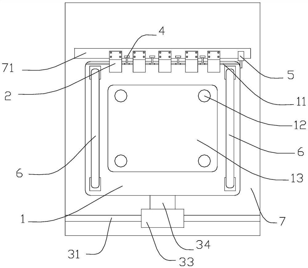
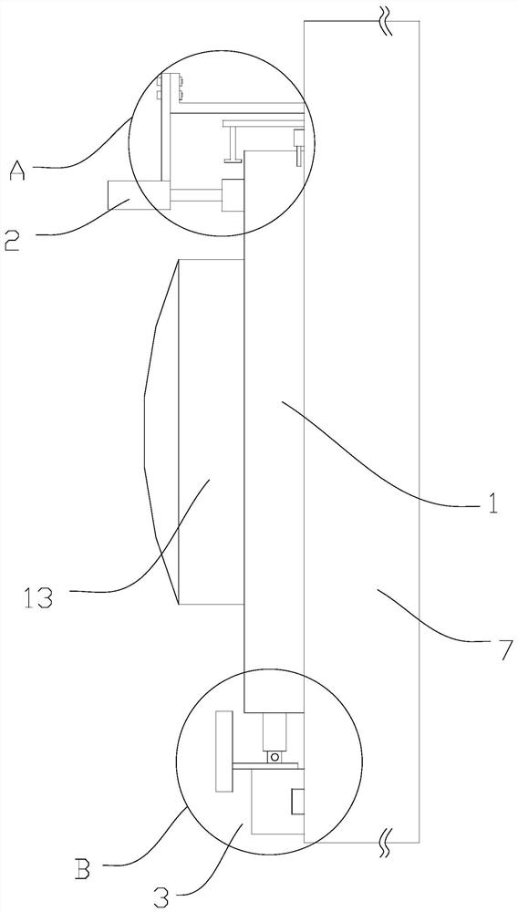
[0032] Such as Figure 1-3 As shown, the door body structure for the vacuum chamber includes a body 1 that can be movably arranged at the opening of the vacuum chamber 7, and the body 1 is used to close the opening of the vacuum chamber 7, so that the vacuum chamber 7 In a sealed state, it can be vacuumized and coated.

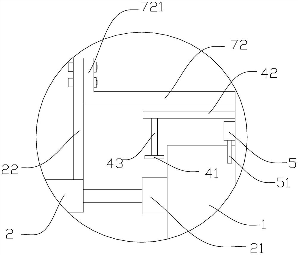
[0033] Wherein, a mounting part 71 is provided on the outer wall of the vacuum chamber 7 above the opening, and a plurality of fixed cylinders 2 are provided on the mounting part 71 .

[0034] When the body 1 coincides with the opening, the fixed cylinder 2 is in contact with the surface of the body 1 to press the body 1 against the outer wall of the vacuum chamber 7 .

[0035] When the body is misaligned with the opening, the fixed cylinder 2 stops working, and the surface of the body 1 obliquely touches the fixed cylinder 2 .

[0036] Wherein, the piston rod of the fixed cylinder 2 is provided with a pressure block 21 for conflicting with the body 1 .

[...

specific Embodiment 2

[0054] Such as Figure 1-4 As shown, the mounting portion 71 is provided with a plurality of limit rods 4, the limit rod 4 is provided with a sliding wheel 41, and the body 1 is provided with a guide that matches the sliding wheel 41. Groove 11.

[0055] Specifically, when the body 1 and the vacuum chamber 7 are disengaged, the body 1 is inclined under the action of the protrusion 13, and the sliding wheel 41 is inserted into the guide groove 11 to play a position-limiting role. , while improving the accuracy and stability of the displacement of the main body 1 .

[0056] Further, the limiting rod 4 is composed of a fixing part 42 and a limiting part 43, which are arranged in the shape of a "7", the fixing part 42 is connected with the installation part 71, and the limiting part 43 is sleeved with the The limiting wheel 41 is described.

[0057] Wherein, the guide device 3 includes a guide rail 31, a slider 32, a baffle plate 33 and a connecting block 34, the guide rail 31 ...


PUM


Abstract

The invention dislcoses a door body structure used for a vacuum chamber. The door body structure comprises a body movably arranged at an opening of the vacuum chamber. A mounting portion is arranged in the position, located above the opening, of the outer wall of the vacuum chamber. A plurality of fixed air cylinders are arranged on the mounting portion and face the vacuum chamber. When the body seals the opening, the ends of the fixed air cylinders abut against the body, and the body is pressed tightly on the outer wall of the vacuum chamber. The bottom of the body is connected with a guide device. The guide device is connected with the body and the vacuum chamber and located below the opening. The door body structure provided by the invention has the advantages of simple structure, convenient and fast disassembling and assembling, stable connection and high state switching efficiency, and the problems that the opening and closing process of the vacuum chamber is tedious and consumes a lot of time and labor due to the complex manual assembling and disassembling of a structure for connecting the vacuum chamber with the door body structure of an existing vacuum coating device are solved.

Description

technical field [0001] The invention relates to the technical field of a vacuum chamber door body structure, in particular to a door body structure for a vacuum chamber. Background technique [0002] The metal coating process needs to vacuumize the coating chamber with a vacuum pump, and then observe the metal coating situation through the observation window on the door structure. At present, the chamber door structure of the metal coating production line is mainly used to seal the coating chamber after the metal steel coil and the feeding car are sent into the coating chamber, so that the coating chamber can be vacuumed for subsequent coating . [0003] Since the connection between the door structure and the coating chamber of the traditional vacuum coating production line must be provided with a connection structure, the door structure requires manual adjustment of the connection structure when switching between opening the coating chamber for feeding and sealing the coat...

Claims


Application Information

Patent Timeline
Patent Type & Authority Applications(China)
IPC IPC(8): C23C14/56C23C14/52C23C16/54
Inventor 刘慧丹陈元缪朴袁尧粟坤乾
Owner ZHAOQING HONGWANG METAL IND
Why Eureka
Try Eureka