
Tracking-free solar concentrating system

A technology of solar concentrating and concentrating mirrors, which is applied in the field of solar concentrating, can solve problems such as solar thermal power generation, and achieve the effects of expanding the scope of application, increasing energy flux density and concentrating ratio

Inactive Publication Date: 2021-04-16
SHANGHAI INST OF APPLIED PHYSICS - CHINESE ACAD OF SCI
View PDF4 Cites 0 Cited by
  • Summary
  • Abstract
  • Description
  • Claims
  • Application Information

AI Technical Summary

Problems solved by technology

But for solar thermal power generation, the system temperature needs to be greater than 300°C, and the concentration ratio should generally be greater than 50. Therefore, although a single CPC can achieve tracking-free, it does not meet the needs of solar thermal power generation

Method used


Image

  • Tracking-free solar concentrating system
  • Tracking-free solar concentrating system
  • Tracking-free solar concentrating system

Examples


Embodiment 1

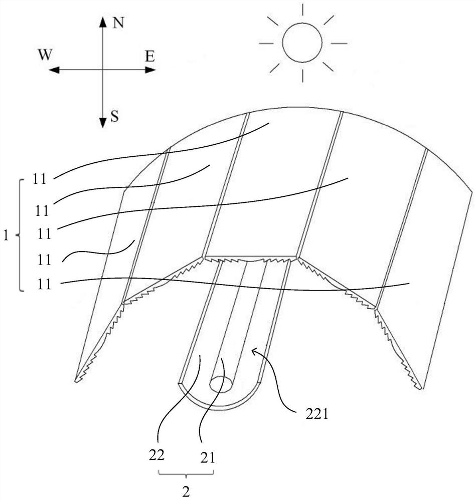
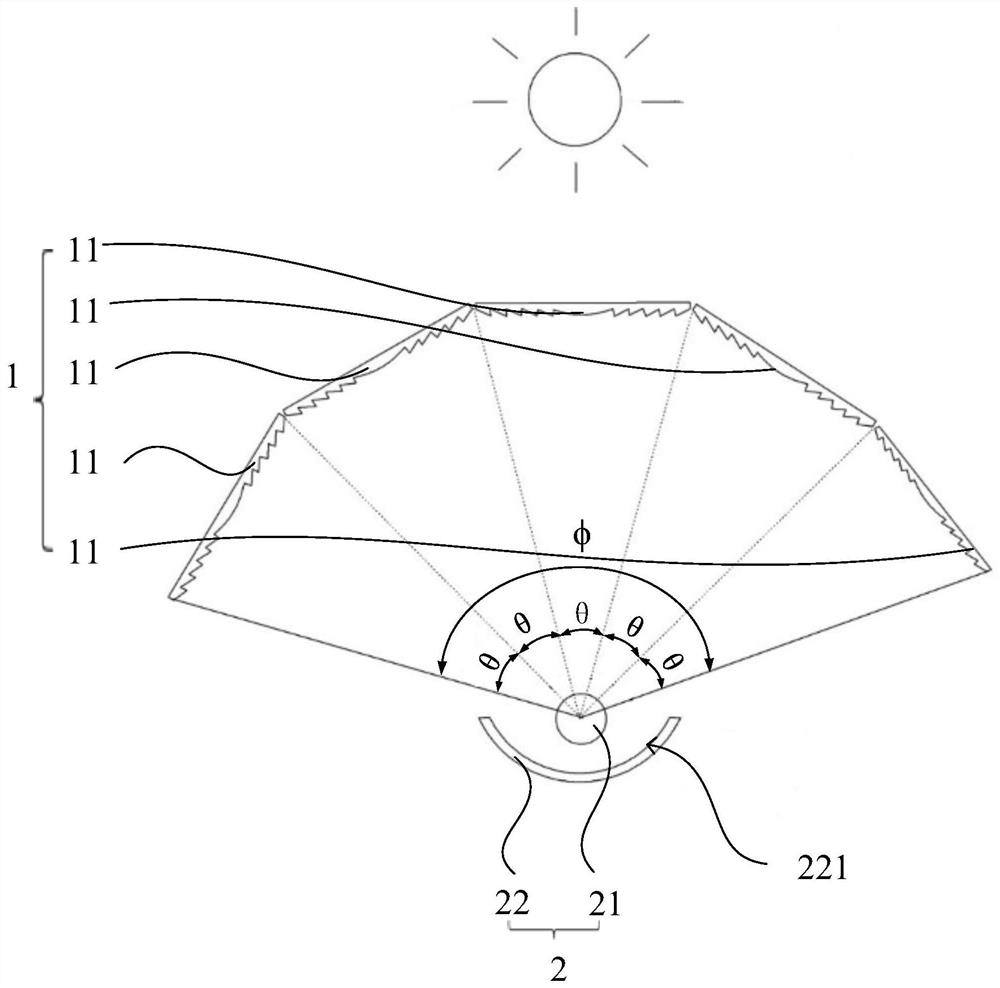
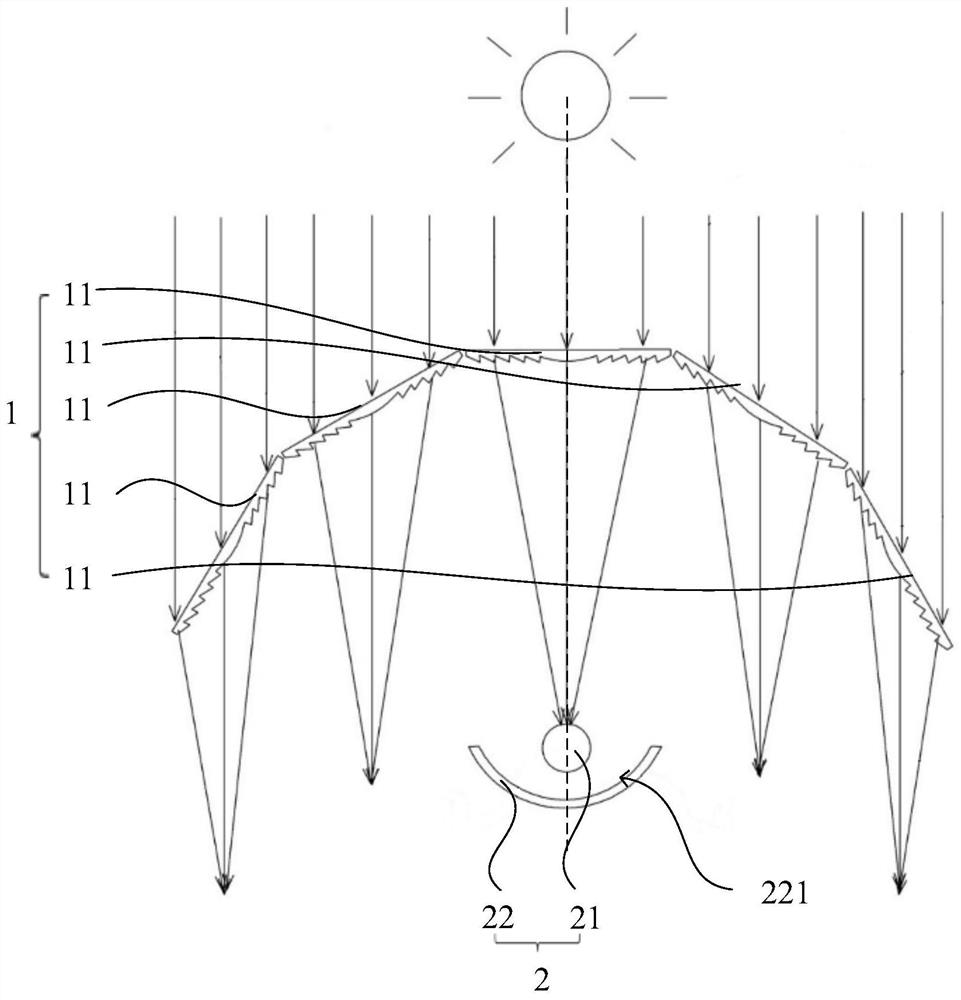
[0044] This embodiment provides a tracking-free solar concentrating system, which is used to collect heat in light in real time without tracking changes in the sun's incident angle. Wherein, the change of the sun incident angle includes the change of the sun altitude angle and the change of the sun azimuth angle. Such as Figure 1-2 As shown, the tracking-free solar concentrating system includes a primary concentrating unit 1 and a heat concentrating unit 2, the primary concentrating unit 1 surrounds the outside of the heat concentrating unit 2, and the light passes through the primary concentrating unit 1 and then focuses to the heat concentrating unit 2 superior.

[0045] The primary concentrating unit 1 includes several transmissive converging lenses 11. In this embodiment, the number of transmissive concentrating lenses 11 of the primary concentrating unit 1 is five, and the five transmissive converging lenses 11 are sequentially spliced ​​to form a primary concentrating ...

Embodiment 2

[0065] The structure of the tracking-free solar concentrating system in Embodiment 2 is basically the same as that in Embodiment 1, except that the arrangement directions of the transmissive concentrators 11 and the heat-gathering parts 2 are different, and the number of transmissive concentrators 11 is different.

[0066] Such as Figure 6 As shown, the transmission condenser 11 in the present embodiment is arranged along the east-west direction, that is, the focal line of the transmission condenser 11 is parallel to the east-west direction, and the heat-absorbing tube 21 and the secondary condenser 22 are also arranged along the east-west direction, and the axes of the heat-absorbing tube 21 are parallel At the focal line of the transmission condenser 11. In this embodiment, the number of transmission condensers 11 is three, and the three transmission condensers 11 are sequentially spliced ​​along the north-south direction to form an arc-shaped primary condenser unit 1 . Wh...


PUM


Abstract

The invention discloses a tracking-free solar concentrating system. The tracking-free solar concentrating system comprises a primary light concentrating unit and a heat concentrating part, wherein the primary light concentrating unit comprises a plurality of transmission light condensers which are sequentially spliced and arranged around the heat concentrating part, light rays penetrate through the transmission light condensers to be focused to form focusing areas, the focusing areas deviate from the passing paths along with the change of the incident angle of the sun to form focal planes, and the focal planes corresponding to the transmission light condensers all pass through the heat concentrating part. Under the irradiation of sunlight at any moment, the focusing area of at least one transmission light condenser always passes through the heat concentrating part. Therefore, under the condition that the heat concentrating part does not move, light rays penetrating through the transmission light condensers can be directly gathered on the heat concentrating part all the time, the energy flow density and the light gathering ratio of light spots focused on the heat concentrating part are greatly improved, the light gathering ratio can meet requirements of solar high-temperature utilization scenes such as solar photo-thermal power generation and the like, and the application range of the tracking-free solar concentrating system is expanded.

Description

technical field [0001] The invention belongs to the field of solar energy concentration, in particular to a tracking-free solar energy concentration system. Background technique [0002] Compared with the grid parity of photovoltaic power generation, the high cost of concentrating light has become a key technical bottleneck restricting the commercialization of solar thermal power generation at this stage. How to improve efficiency and reduce costs on a large scale is the development trend and direction of solar thermal power generation. The solar concentrator is a key component of a solar thermal power plant, and its cost accounts for more than 40% of the total cost of the plant. Solar concentrators are generally large glass reflectors, and in order to facilitate processing and production, they usually adopt a spliced ​​concentrating structure. Since the incident angle of sunlight changes with time, the concentrator needs to be equipped with a one-dimensional or two-dimens...

Claims


Application Information

Patent Timeline
Patent Type & Authority Applications(China)
IPC IPC(8): F24S23/30F24S23/70F24S10/70
CPCY02E10/44
Inventor 肖君曹云韩利峰
Owner SHANGHAI INST OF APPLIED PHYSICS - CHINESE ACAD OF SCI
Learn More