Electrical control cabinet for intelligent building
A technology for electrical control cabinets and buildings, applied in vibration suppression adjustment, cleaning methods and utensils, cleaning methods using tools, etc., can solve the problems of inconvenient control of the temperature of electrical cabinets, no cleaning device, short circuit of electronic components inside the control cabinet, etc.
- Summary
- Abstract
- Description
- Claims
- Application Information
AI Technical Summary
Problems solved by technology
Method used
Image


Examples
Embodiment 1
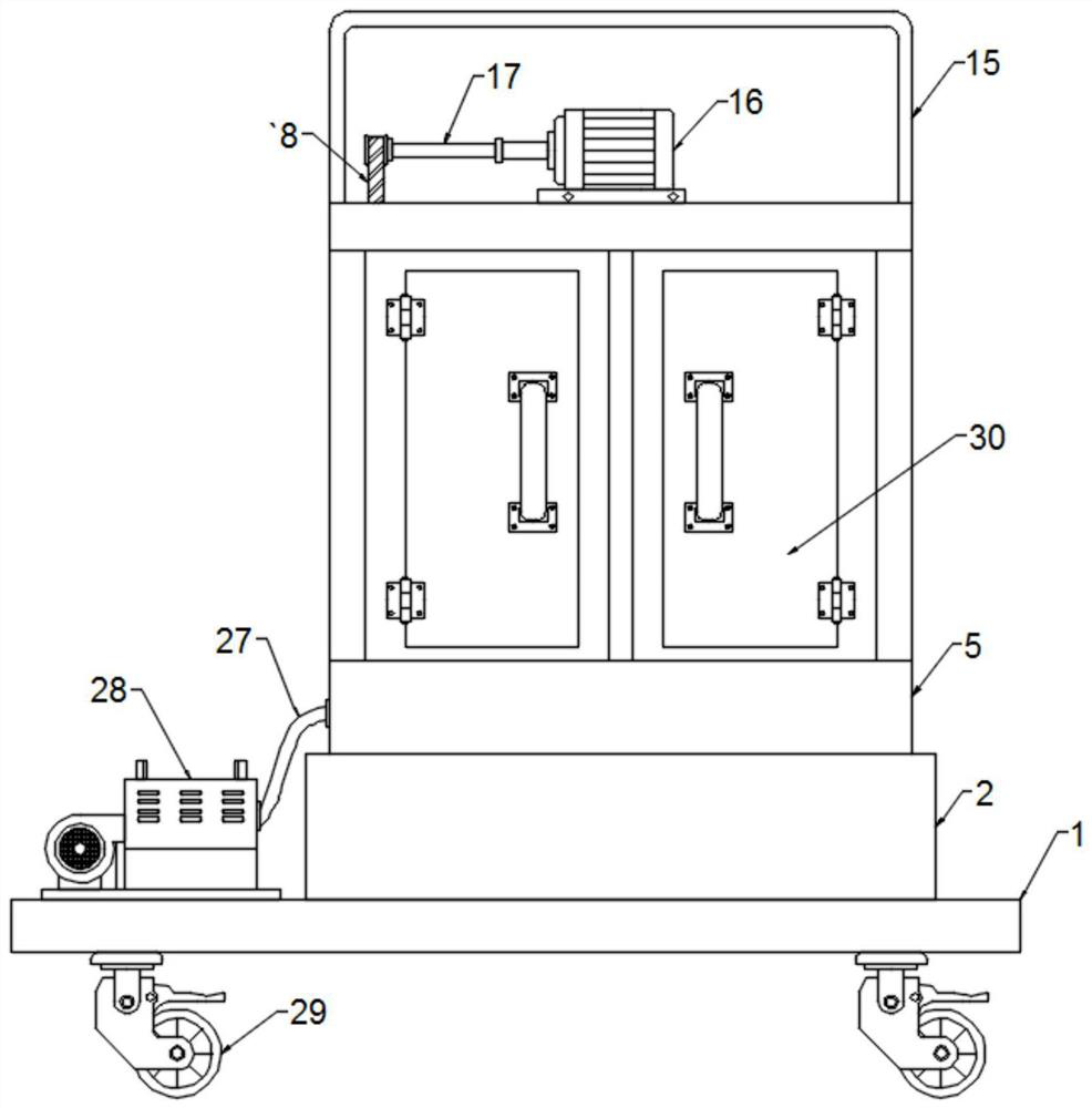
[0026] refer to Figure 1-4 , an electrical control cabinet for intelligent buildings, comprising a base 1, a cabinet 5 is arranged on the top of the base 1, a component assembly frame 11 is fixedly connected to the center of the bottom of the inner cavity of the cabinet 5, and the top of the cabinet 5 is fixedly connected to a Drive motor 16, the output shaft transmission of drive motor 16 is connected with transmission rod 17, and the upper part of one side of the cabinet body 5 inner chamber is connected with connecting column 19 through rotating shaft rotation, and the transmission rod 17 and connecting column 19 are wound and connected by belt 18. One side of the body 5 top is provided with a belt hole 32 for use with the belt 18, and one end of the connecting column 19 is fixedly connected with a disc 20, and the side of the disc 20 away from the connecting column 19 is fixedly connected with a small cylinder 21, and the small cylinder 21 is located at On the outer wall ...
Embodiment 2
[0028] refer to Figure 1-4A temperature sensor 14 is fixedly connected to one side of the top of the component assembly frame 11, a temperature controller 13 is fixedly connected to the middle of the top, and a battery pack 12 is fixedly connected to the other side of the top, and the cabinet body 5 is far away from the vent 24. One side is provided with a heat dissipation hole 7 used in conjunction with the component assembly frame 11, a fan 8 is installed in the heat dissipation hole 7, and the inner cavity of the cabinet body 5 is provided with a bearing frame 10, and one side of the bearing frame 10 communicates with the heat dissipation hole 7, The inner side of the bearing frame 10 is fixedly connected with a semiconductor refrigerator 9, and the side of the bearing frame 10 close to the component assembly frame 11 is provided with several through holes 31, and the side of the inner cavity of the cabinet body 5 away from the vent 24 is fixedly connected with a mating com...
Embodiment 3
[0030] refer to Figure 1-4 , the bottom of the cabinet 5 is set with a shock absorbing frame 2, and the bottom of the shock absorbing frame 2 is fixedly connected to the top of the base 1, and the two sides of the bottom of the cabinet 5 and the inner top sides of the shock absorbing frame 2 pass through Several extrusion springs 3 are fixedly connected, and the distance between every two adjacent extrusion springs 3 is equal, and the middle part of the bottom of the cabinet body 5 and the middle part of the inner top of the shock absorbing frame 2 pass through several first telescopic rods 4 Fixedly connected, and the distance between every two adjacent first telescopic rods 4 is equal, the extension length of the first telescopic rods 4 is less than the height of both sides of the shock absorbing frame 2, and the four corners at the bottom of the base 1 are fixedly connected with The universal self-locking wheel 29, specifically, through the cooperation between the shock ab...
PUM
 Abstract
Description
Claims
Application Information
 - R&D
- Intellectual Property
- Life Sciences
- Materials
- Tech Scout
- Unparalleled Data Quality
- Higher Quality Content
- 60% Fewer Hallucinations
Browse by: Latest US Patents, China's latest patents, Technical Efficacy Thesaurus, Application Domain, Technology Topic, Popular Technical Reports.
© 2025 PatSnap. All rights reserved.Legal|Privacy policy|Modern Slavery Act Transparency Statement|Sitemap|About US| Contact US: help@patsnap.com