
partial arc cut stapler

A stapler and local technology, applied in the field of medical machinery, can solve the problems of small resection chamber, low selectivity, poor flexibility of the stapler, etc., and achieve the effects of reducing cutting, enhancing practicability, and improving cutting efficiency

Active Publication Date: 2021-10-26
QIANFOSHAN HOSPITAL OF SHANDONG
View PDF12 Cites 0 Cited by
  • Summary
  • Abstract
  • Description
  • Claims
  • Application Information

AI Technical Summary

Problems solved by technology

[0003] Disposable arc cutting stapler in Patent No. CN111407340A discloses a disposable arc cutting stapler, including a stapler body, one end of the stapler body is provided with a connecting block, the connecting block is connected with a push rod through a guide sleeve, and the connecting block One end is fixed with an arc-shaped splint, and the upper end of the arc-shaped splint is welded and fixed with a nail seat; by setting a rotating plate, a slider, a limit groove, a second limit block, a first limit block and an installation block, it is avoided. Pulling the firing lever causes the positioning needle inside the positioning nail magazine to move, which improves the safety of the equipment. By setting up protective silicone blocks, grooves and clamping blocks, the surface on the side of the nail seat is covered to avoid direct contact with the surface of the nail seat. Exposed to the air, it is easily contaminated by external bacteria, but the stapler disclosed in this patent has poor flexibility, and at the same time, the resection chamber is small, and the selectivity is low. Therefore, a local arc-cut stapler with high flexibility is urgently needed

Method used


Image

  • partial arc cut stapler
  • partial arc cut stapler
  • partial arc cut stapler

Examples


Embodiment 1

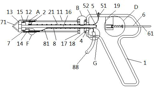
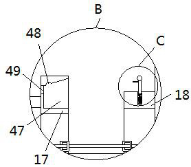
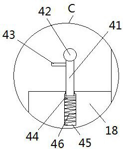
[0041] See Figure 1-11 The present invention provides a technical solution: a partial arc crust, including a gun body 1 and anastomot tube 11, a gun body 1 is a hollow gun body, an anastomot tube 11 is a semi-circular hollow arcuate tube, an anastomot tube 11 The positioning plate A17 is fixed to the right end face, and the positioning plate B18 is fixedly mounted on the left end surface of the gun body 1, and the left end of the positioning plate B18 is disposed on the right side of the positioning plate A17, on the left end face of the anastomot tube 11 Two first restricted rods 12 and a second restricted bit rod 7 are provided, and the two first limiting rods 12 are located on both ends of the left end surface of the anastomot tube 11, and the second residential bit rod 7 is located located close. On the left end surface of the anastomot tube 11 of the lower first limiting rod 12, between the second restricted bit rod 7 and the upper first residential rod 12 about the extension...

Embodiment 2

[0044] See Figure 12 On the basis of the example one, a rotary button 92 is provided in the gun body 1, the rotary button 92 rotates in the anorectal by controlling the movable plate 13, thereby achieving the effect of cutting acne, the rotary button 92 is existing Technology, in the patent number CN206261634U disposable anorectal using anastomosis, it has been disclosed, and details are not described herein.

[0045] At the time of use, at the bottom of the target of the gun body 1, the left end of the movable plate 13 and the anastomot tube 11 extends into the human body, and the cone plate 71 is a tapered, more gains into the anorectal cavity, into the gun After the body 1 is slowly pushed, the push rod 61 is pushed, the push rod 61 is pushed on the link 63, and the linkage plate 63 is pushed to the permanent magnet B66, and the permanent magnet B66 is opposite to the magnetic pole of the permanent magnet A52. Normally, the jack 62 and the permanent magnet B66 are in a close fi...


PUM


Abstract

The invention relates to the technical field of medical machinery, and discloses a local arc-cut stapler, which includes a gun body and an anastomotic tube. The anastomotic tube is a semicircular hollow arc-shaped tube. The two first limit rods are respectively located on the upper and lower sides of the left end surface of the anastomotic tube, and the second limit rod is arranged on the left side of the anastomotic tube near the first limit rod on the lower side On the end face, the included angle between the second limit rod and the upper first limit rod with respect to the extension line at the center of the anastomotic tube is 120 degrees. In the local arc-cutting stapler, the present invention sets the first stop bar, the second stop bar and the baffle plate, and the first stop bar, the second stop bar and the baffle plate can all cut the normal anorectal inner wall when hemorrhoids are cut. The mucous membrane has the effect of limiting and blocking, and the angle of the anorectal inner wall after cutting the hemorrhoids through the first limiting rod and the second limiting rod can be 120 degrees and 60 degrees, which improves the selectivity of the present invention for cutting hemorrhoids .

Description

Technical field [0001] The present invention relates to the field of medical mechanical technology, in particular a partial arc anastomosis. Background technique [0002] Patients with hemorrhoids often need surgery to remove acne, and acne cutting equipment is generally anastomosis, and the stapler generally refers to a hollow tube inserted into the patient's body, and the stapler is connected to the surgical gun body. The surgical gun body is provided with a handle, which is convenient for the attending physician to take, and the other end of the stapler is provided with a hook that hooks acne and cutting blades for hemorrhoids. However, in the process of use, there is often a disadvantage in the process of use, which is to make the hemorrhoids in the analgesia, and the acne is tied. The mucosa on the inner wall of the anorectal wall is pulled into the anastomotic cavity, causing the cutting blade to cut the mucosa in the anorectal wall. Therefore, for the above problems, there...

Claims


Application Information

Patent Timeline
Patent Type & Authority Patents(China)
IPC IPC(8): A61B17/3209A61B17/11A61B90/17
Inventor 李涛
Owner QIANFOSHAN HOSPITAL OF SHANDONG
Learn More