Inertial navigation pose precision adjusting and mounting device for unmanned aerial vehicle

A technology for installing devices and UAVs, which is applied in aircraft assembly, measuring devices, instruments, etc., and can solve problems such as inability to meet UAV inertial navigation installation accuracy measurement requirements, low measurement devices, and short UAV assembly cycle.

Pending Publication Date: 2021-04-20
XIAN AISHENG TECH GRP
View PDF9 Cites 1 Cited by
  • Summary
  • Abstract
  • Description
  • Claims
  • Application Information

AI Technical Summary

Problems solved by technology

[0004] Due to the smaller outline size of the UAV fuselage structure and equipment, there is a size limit for the adjustment device. In addition, the systematic error of the measurement system has a greater impact on the relative error of the inertial navigation attitude accuracy, and the assembly cycle of the UAV is longer. Short, the above disclosed technology cannot meet the precision measurement requirements of UAV inertial navigation installation in mass production in terms of the accuracy and efficiency of the measurement method and the low cost and convenience of the measurement device.
The fixed connection link with the fuselage after the inertial navigation adjustment is completed is also a factor that affects the final installation accuracy of the inertial navigation, and none of the above-mentioned disclosed technologies involves this aspect

Method used


Image

  • Inertial navigation pose precision adjusting and mounting device for unmanned aerial vehicle
  • Inertial navigation pose precision adjusting and mounting device for unmanned aerial vehicle
  • Inertial navigation pose precision adjusting and mounting device for unmanned aerial vehicle

Examples


Embodiment Construction

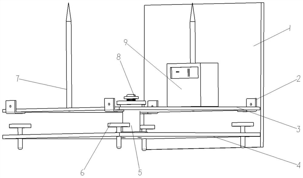
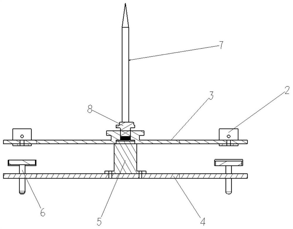
[0032] This embodiment is an installation device for adjusting the pose accuracy of UAV inertial navigation.

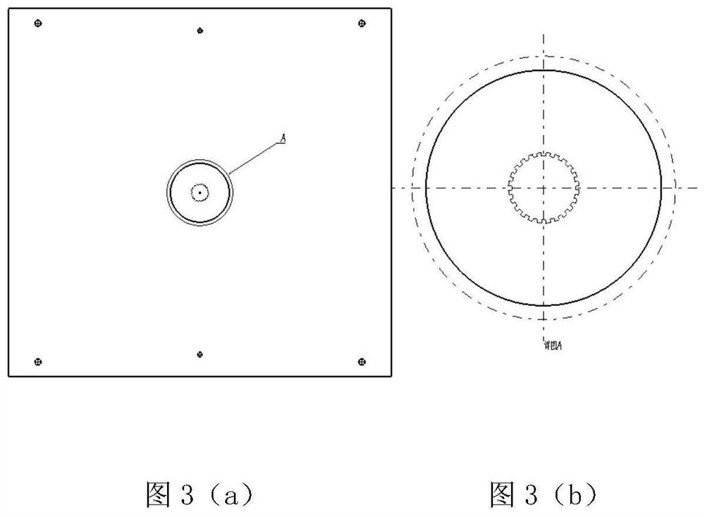
[0033] refer to Figure 1 to Figure 7 , the present embodiment is used for the UAV inertial navigation position and attitude adjustment installation device, which consists of a fuselage frame plate 1, a connecting joint 2, an inertial navigation installation template 3, a bottom plate 4, a connecting column 5, a horizontal adjustment screw 6, and a heading indicator rod 7. The course adjustment rod 8, the electronic level 9, the optical level 10 and the optical theodolite 11 are composed; wherein, the inertial navigation installation template 3 is located at the upper end of the connecting column 5, and the inertial navigation installation template 3 and the connecting column 5 are clearance fit, which can Rotate around connecting column 5. The bottom plate 4 is fixedly connected with the bottom surface of the connecting column 5 by bolts. The contour dimensions of ...


PUM


Abstract

The invention discloses an inertial navigation pose precision adjusting and mounting device for an unmanned aerial vehicle, the device can quickly and effectively adjust the mounting precision of inertial navigation equipment of the unmanned aerial vehicle and is accurately connected with a fuselage frame plate. A horizontal adjusting screw of the inertial navigation pose adjusts the height of a bottom plate through a thread pair, a course adjusting rod is installed in a steering groove in the center of an inertial navigation installation sample plate, the course adjusting rod rotates to drive a gear ring in the steering groove to rotate, and course adjustment of the inertial navigation installation sample plate is achieved. The precision grade of a course indication rod of the inertial navigation installation sample plate meets the horizontal measurement requirement of the unmanned aerial vehicle for an optical level meter and an optical theodolite, and the minimum measurement resolution of the electronic digital display gradienter is higher than the inertial navigation installation precision requirement. The inertial navigation pose precision adjusting and mounting device is simple in structure and convenient to operate; the device is suitable for unmanned aerial vehicles of various types and sizes, facilitates maintenance and use, is high in measurement result precision and convenient to read, guarantees the navigation precision of the unmanned aerial vehicle in the flight process, and provides guarantee for the unmanned aerial vehicle to complete flight tasks.

Description

technical field [0001] The invention relates to the technical field of unmanned aerial vehicle assembly, in particular to an inertial navigation pose precision adjustment installation device for the general assembly of unmanned aerial vehicles. Background technique [0002] Due to the characteristics of reducing the risk of operators, low cost, strong ability to perform tasks and good operability, UAVs have become the new darling of modern warfare in recent years. In modern advanced UAVs, the inertial navigation system, as the core information source of navigation, flight control and fire control systems, directly affects the completion of combat missions and flight safety. Ensuring the accurate installation of the drone's inertial navigation components is the premise and basis for ensuring the positioning accuracy of the drone. However, the installation of existing UAV equipment fails to focus on the installation accuracy of inertial navigation, and it can no longer meet t...

Claims


Application Information

Patent Timeline
Patent Type & Authority Applications(China)
IPC IPC(8): G01C25/00B64F5/10
Inventor 李诚童话杨柳高星海田少岗
Owner XIAN AISHENG TECH GRP
Why Eureka
Try Eureka