Area array sweep frequency measurement device and method

A measurement device and frequency sweeping technology, applied in the direction of measurement devices, optical devices, radio wave measurement systems, etc., can solve problems such as unsuitable measurement devices

Pending Publication Date: 2021-04-20
武汉光目科技有限公司
View PDF0 Cites 1 Cited by
  • Summary
  • Abstract
  • Description
  • Claims
  • Application Information

AI Technical Summary

Problems solved by technology

The existing speckle suppression technology is to add a dither to the object, which is mainly used in

Method used


Image

  • Area array sweep frequency measurement device and method
  • Area array sweep frequency measurement device and method
  • Area array sweep frequency measurement device and method

Examples


Embodiment 1

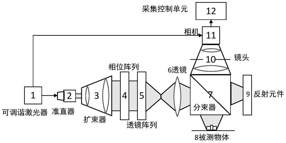
[0053] Such as figure 1 The figure shows an area-array frequency-sweep measurement device for suppressing speckle, including a tunable laser 1, a collimator 2, a beam expander 3, a phase array 4, a lens array 5, a first lens 6, and a beam splitter 7 , lens 10, camera 11, acquisition control unit 12 and reflective element 9;

[0054] On the transmission direction of the laser beam, a collimator 2, a beam expander 3, a phase array 4, a lens array 5, a first lens 6, a beam splitter 7 and a reflective element are sequentially arranged; The direction is arranged in turn with the lens 10 and the camera 11; the output end of the tunable laser 1 is connected to the camera 11;

[0055] The tunable laser 1 is used to control the camera to collect the interference image by sending a trigger signal, and to provide the laser beam; the collimator 2 is used to collimate the divergent laser beam output by the tunable laser 1 into parallel light; the beam expander 3 is used to The parallel l...

Embodiment 2

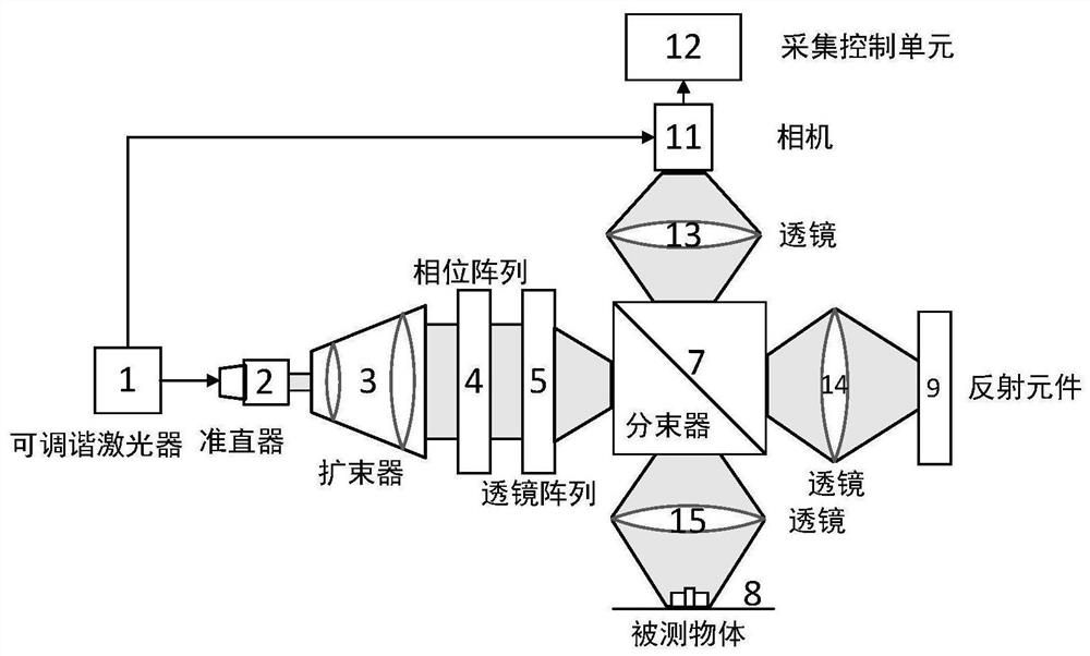
[0068] Such as figure 2 The figure shows an area-array frequency-sweep measurement device for suppressing speckle, including a tunable laser 1, a collimator 2, a beam expander 3, a phase array 4, a lens array 5, a beam splitter 7, and a second lens 15 , the third lens 14, the fourth lens 13, the camera 11, the acquisition control unit 12 and the reflective element 9;

[0069] Collimator 2, beam expander 3, phase array 4, lens array 5, beam splitter 7, third lens 14 and reflective element 9 are arranged successively on the transmission direction of laser beam; The second lens 15, the beam splitter 7, the fourth lens 13 and the camera 11 are arranged in sequence in the direction; the output end of the tunable laser 1 is connected to the camera 11;

[0070] The tunable laser 1 is used to control the camera to collect the interference image by sending a trigger signal, and to provide the laser beam; the collimator 2 is used to collimate the divergent laser beam output by the tun...


PUM


Abstract

The invention provides an area array sweep frequency measurement device and method, and belongs to the technical field of laser ranging. The device comprises a tunable laser, a collimator, a beam expander, a phase array, a lens array, a first lens, a beam splitter, a lens, a camera, an acquisition control unit, and a reflection element. The tunable laser is used for providing a laser beam; the phase array is used for carrying out phase modulation on the expanded parallel light; the lens array is used for focusing the light beams output by each phase array; the beam splitter is used for splitting the light beam output by the first lens into reflection light and transmission light; the reflection element is used for reflecting the transmission light to form reference light; during working, a measured object reflects reflection light to form signal light; the signal light and the reference light interfere to form an interference pattern; the camera is used for collecting the interference image; and the acquisition control unit is used for analyzing the surface topography of the measured object according to the interference image. Through superposition of a plurality of independent speckles, the effect of reducing the speckle contrast is achieved.

Description

technical field [0001] The invention belongs to the technical field of laser distance measurement, and more specifically relates to an area array frequency sweep measurement device and method. Background technique [0002] In modern industrial production, the precision of parts processing has become more and more the key to high-performance equipment. It is very important to accurately and stably produce the required parts of specific size and shape. Therefore, accurate detection of the produced parts is an important link to ensure high-quality production. In the existing technology, accurate distance measurement in a large field of view often requires point-by-point scanning to obtain the shape of the part, and the measurement speed is also limited by the scanning speed, making it difficult to obtain high measurement speed with high sensitivity. [0003] When the area array frequency-sweeping interferometry device is used alone, speckles will appear due to the strong coher...

Claims


Application Information

Patent Timeline
IPC IPC(8): G01S17/08G01S7/481G01B11/06
Inventor 于龙雷力殷晓君鄢淦威陈哲锋
Owner 武汉光目科技有限公司
Why Eureka
Try Eureka