Anti-vibration area array sweep frequency measurement device and method

A measurement device and frequency sweeping technology, which is applied in the direction of measurement devices, optical devices, radio wave measurement systems, etc., can solve problems such as unavoidable vibration and temperature fluctuations, and low measurement accuracy

Pending Publication Date: 2021-04-20
武汉光目科技有限公司
View PDF0 Cites 0 Cited by
  • Summary
  • Abstract
  • Description
  • Claims
  • Application Information

AI Technical Summary

Problems solved by technology

[0004] In view of the defects of the prior art, the object of the present invention is to provide an anti-vibration area array frequency sweep measurement device and method, aiming to solve the problem that the existing frequency sweep interference distance measurement is difficult to avoid vibration and temperature fluctuations, resulting in low measurement accuracy question

Method used


Image

  • Anti-vibration area array sweep frequency measurement device and method
  • Anti-vibration area array sweep frequency measurement device and method
  • Anti-vibration area array sweep frequency measurement device and method

Examples


Embodiment 1

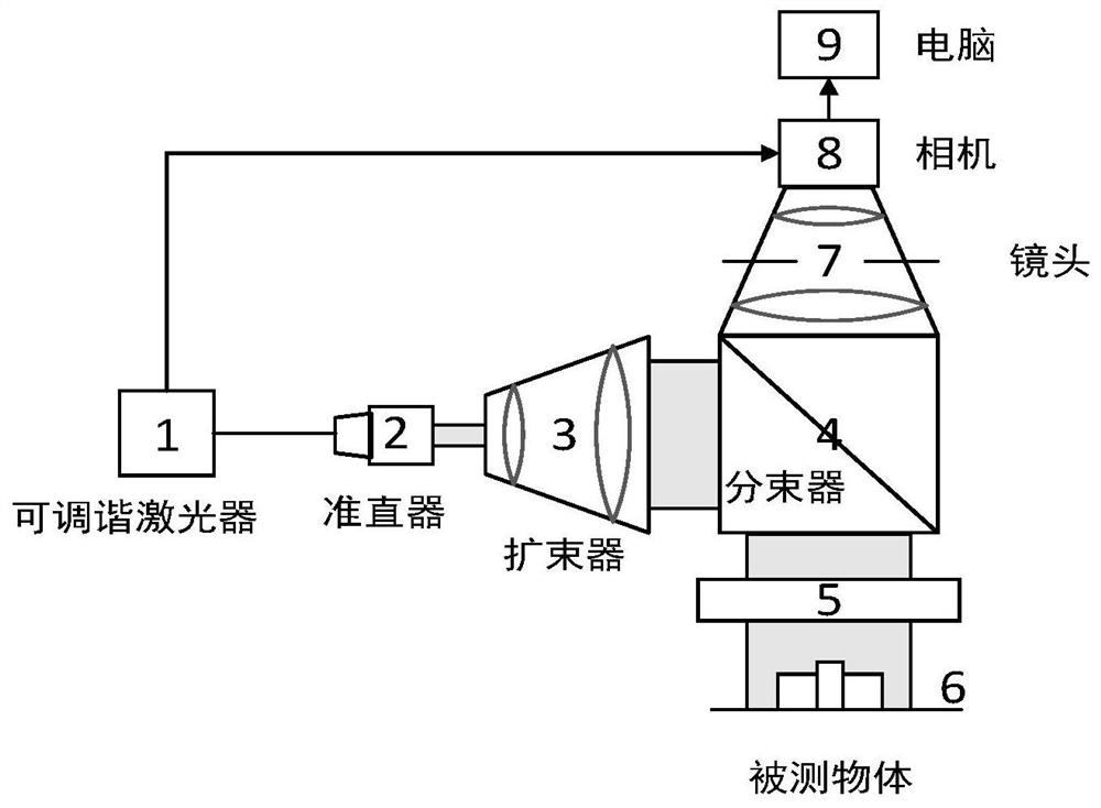
[0046] Such as figure 1 An anti-vibration type area array frequency sweep measurement device is provided as shown, including a tunable laser 1, a collimator 2, a beam expander 3, a beam splitter 4, a reflective element 5, a lens 7, a camera 8 and a computer 9;

[0047] A collimator 2, a beam expander 3, and a beam splitter 4 are sequentially arranged in the transmission direction of the original beam; a reflective element 5, a beam splitter 4, and a lens 7 are sequentially arranged in the direction in which the original beam is reflected by the beam splitter 4 and the camera 8; the output end of the tunable laser 1 is connected to the input end of the camera 8; the measured object 6, the reflective element 5 and the beam splitter 4 are sequentially connected through a rigid structure;

[0048] The process of changing the wavelength of the output wavelength of the tunable laser 1 with time is called optical frequency scanning, referred to as frequency sweeping; A trigger signa...

Embodiment 2

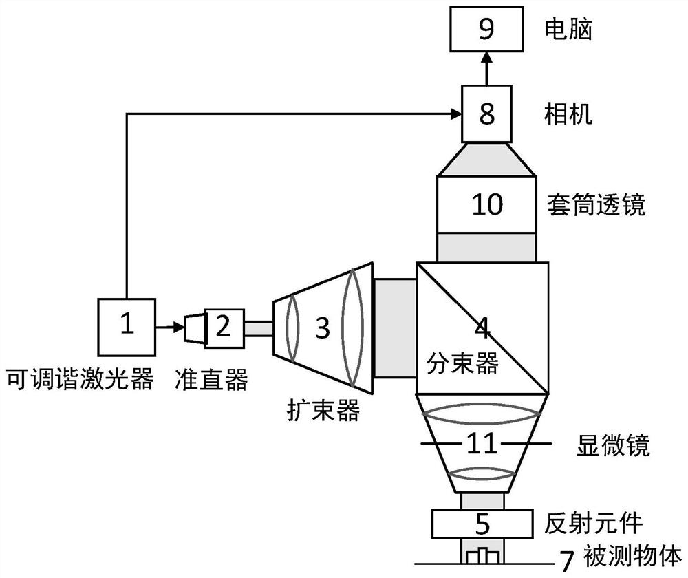
[0059] Such as figure 2 As shown, an anti-vibration area array frequency sweep measurement device is provided, including a tunable laser 1, a collimator 2, a beam expander 3, a beam splitter 4, a reflective element 5, a microscope 11, a tube lens 10, and a camera 8 and computer 9;

[0060] A collimator 2, a beam expander 3, and a beam splitter 4 are sequentially arranged in the transmission direction of the original beam; a reflective element 5, a microscope 11, and a beam splitter 4 are sequentially arranged in the direction in which the original beam is reflected by the beam splitter 4 , a sleeve lens 10 and a camera 8; the output end of the tunable laser 1 is connected to the input end of the camera 8; the measured object 6, the reflective element 5 and the microscope 11 are sequentially connected through a rigid structure;

[0061] The process of changing the wavelength of the output wavelength of the tunable laser 1 with time is called optical frequency scanning, referr...

Embodiment 3

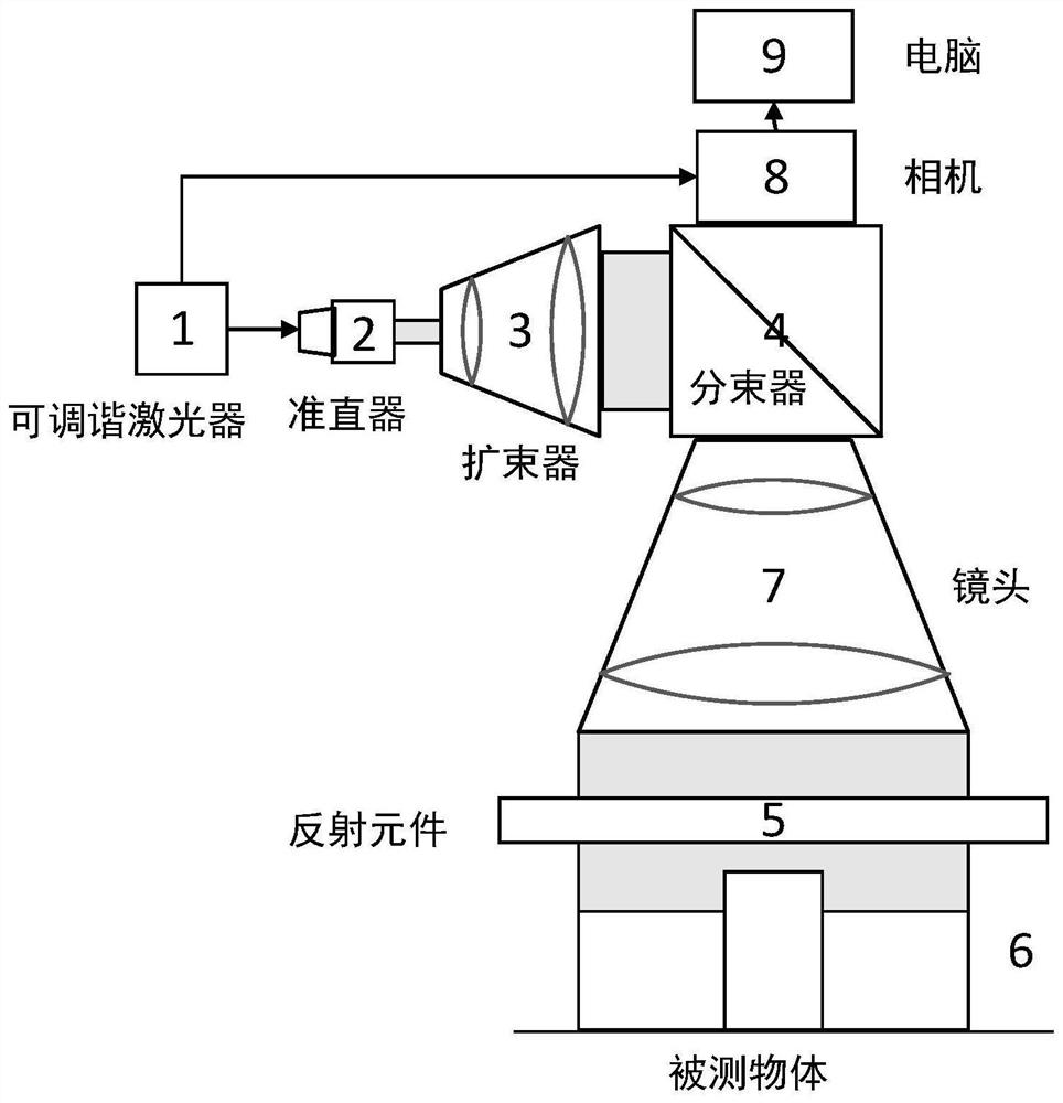
[0065] Such as figure 1 An anti-vibration type area array frequency sweep measurement device is provided as shown, including a tunable laser 1, a collimator 2, a beam expander 3, a beam splitter 4, a reflective element 5, a lens 7, a camera 8 and a computer 9;

[0066] A collimator 2, a beam expander 3, and a beam splitter 4 are sequentially arranged in the transmission direction of the original beam; a reflective element 5, a lens 7, and a beam splitter 4 are sequentially arranged in the direction in which the original beam is reflected by the beam splitter 4 and the camera 8; the output end of the tunable laser 1 is connected to the input end of the camera 8; the measured object 6, the reflective element 5 and the beam splitter 4 are sequentially connected through a rigid structure;

[0067] The process of changing the wavelength of the output wavelength of the tunable laser 1 with time is called optical frequency scanning, referred to as frequency sweeping; A trigger signa...


PUM


Abstract

The invention provides an anti-vibration area array sweep frequency measurement device and method, and belongs to the technical field of laser ranging. The device comprises a tunable laser, a collimator, a beam expander, a beam splitter, a reflection element, a lens, a camera, and an acquisition control unit. The tunable laser is used for controlling the camera to acquire an interference image by sending a trigger signal and providing an original light beam; the beam splitter is used for reflecting the original light beam to the reflecting element; the reflection element is used for reflecting the original light beam according to a certain proportion to form reference light and transmitting the last residual original light beam to a measured object; the measured object is used for reflecting the last residual original light beam to form signal light; the lens is used for imaging an interference image on the camera; the acquisition control unit is used for analyzing the surface topography of the measured object according to the interference image; the signal light interferes with the reference light to form an interference image. According to the invention, the anti-vibration effect of the area array sweep frequency measurement device is improved, and the measurement accuracy is further improved.

Description

technical field [0001] The invention belongs to the technical field of laser distance measurement, and more specifically relates to an anti-vibration area array frequency sweep measurement device and method. Background technique [0002] In modern industrial production, the precision of parts processing has become more and more the key to high-performance equipment. It is very important to accurately and stably produce the required parts of specific size and shape. Therefore, accurate detection of the produced parts is an important link to ensure high-quality production. In the existing technology, it is often necessary to obtain the shape of the part through point-by-point scanning. Although the measurement range is expanded, the measurement process relies on mechanical movement, which will inevitably introduce mechanical scanning errors, and will also make the equipment face aging of moving parts, Instability and other issues. Moreover, the measurement speed will be limi...

Claims


Application Information

Patent Timeline
IPC IPC(8): G01S17/08G01S7/481G01B11/06
Inventor 于龙殷晓君雷力谢谊李志标
Owner 武汉光目科技有限公司
Why Eureka
Try Eureka