Antirust treatment device for elevator part machining

A technology for anti-rust treatment and parts, which is applied in the direction of spraying devices, etc., can solve the problems of parts corrosion, affect the reliability of elevators, and the inability to achieve uniform painting, etc., to achieve good user experience, improved painting adequacy, and simple structure Effect

Pending Publication Date: 2021-04-23
方冬荣
View PDF7 Cites 4 Cited by
  • Summary
  • Abstract
  • Description
  • Claims
  • Application Information

AI Technical Summary

Problems solved by technology

[0003] The elevator is composed of many parts, some of which need to be coated with grease for anti-rust treatment, but there are also some parts that need to be sprayed with anti-rust paint, so as to prolong the rust process of the parts and extend the service life of the elevator. However, some of the existing painting equipment is being painted In the process of spraying, the paint cannot be sprayed evenly, which will lead to corrosion of parts and affect the reliability of the elevator

Method used


Image

  • Antirust treatment device for elevator part machining
  • Antirust treatment device for elevator part machining
  • Antirust treatment device for elevator part machining

Examples


Embodiment 1

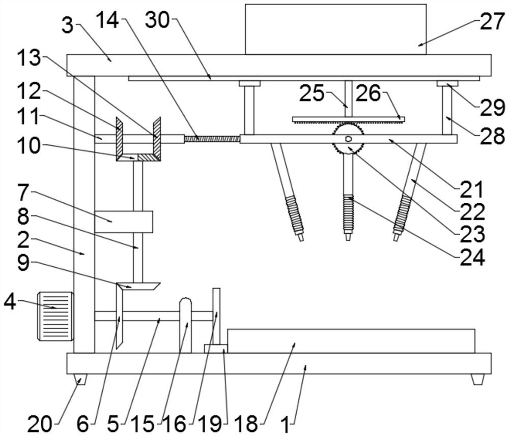
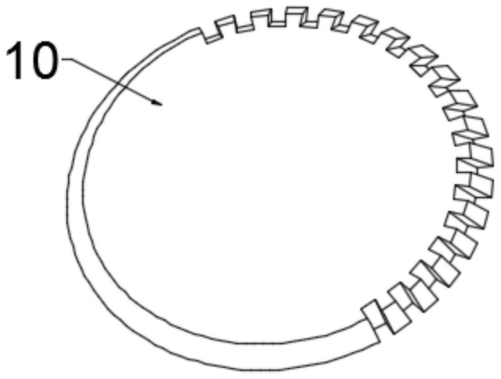
[0025] Example 1: Please refer to Figure 1-4 , an antirust treatment device for elevator parts processing, comprising a fixed base 1, a column 2 is fixedly connected to the left side above the fixed base 1, an upper beam 3 is fixedly connected to the top of the column 2, and an upper beam 3 is fixedly connected to the bottom left side of the column 2. The motor 4 is fixedly connected to the output shaft of the motor 4 with a drive shaft 5, the outside of the drive shaft 5 is fixedly connected with a first bevel gear 6, the right side of the column 2 is fixedly connected with a guide bracket 7, and the inside of the guide bracket 7 is rotatably connected with a transmission shaft 8. The bottom of the transmission shaft 8 is fixedly connected with a second bevel gear 9, the second bevel gear 9 meshes with the first bevel gear 6, and the top of the transmission shaft 8 is fixedly connected with an incomplete bevel gear 10;

[0026] Turn on the motor 4 during use, the rotation of...

Embodiment 2

[0039] Embodiment 2: This embodiment is a further improvement of the previous embodiment: a sliding guide rod 28 is fixedly connected above the sliding paint spraying board 21, a slider 29 is fixedly connected above the sliding guide rod 28, and a sliding block 29 is fixedly connected below the upper beam 3. The guide chute 30 and the slider 29 are slidably connected to the guide chute 30 , and the cooperation between the slider 29 and the guide chute 30 can achieve a good guiding effect.

[0040] The working principle of the present invention is: turn on the motor 4 during use, the rotation of the motor 4 drives the drive shaft 5 to rotate, the rotation of the drive shaft 5 drives the first bevel gear 6 to rotate, the rotation of the first bevel gear 6 drives the rotation of the second bevel gear 9, and then drives The incomplete bevel gear 10 rotates, and the incomplete bevel gear 10 alternately meshes with the third bevel gear 12 and the fourth bevel gear 13, thereby realizi...


PUM


Abstract

The invention discloses an antirust treatment device for elevator part machining, and relates to the field of elevator part machining. The antirust treatment device comprises a fixed base, wherein a stand column is fixedly connected to the left side of the upper portion of the fixed base, an upper beam is fixedly connected to the top of the stand column, a motor is fixedly connected to the lower portion of the left side of the stand column, a driving rotating shaft is fixedly connected to an output shaft of the motor, a first bevel gear is fixedly connected to the outer side of the driving rotating shaft, a guide support is fixedly connected to the right side of the stand column, a transmission rotating shaft is rotationally connected to the inner side of the guide support, and a second bevel gear is fixedly connected to the bottom of the transmission rotating shaft. A paint spraying assembly is driven by the single motor to do left-right reciprocating motion, the paint spraying assembly drives a supporting bottom plate to move front and back while doing left-right reciprocating motion, then paint spraying treatment is carried out in cooperation with the paint spraying assembly, and paint can be fully and evenly sprayed; and in addition, the paint spraying assembly is provided with a directional paint spraying gun and a direction-changing paint spraying gun during paint spraying, the paint spraying sufficiency is greatly improved through cooperative use, and the use experience is good.

Description

technical field [0001] The invention relates to the field of elevator parts processing, in particular to an antirust treatment device for elevator parts processing. Background technique [0002] Elevator refers to the permanent transportation equipment that serves several specific floors in the building, and its car runs on at least two rigid rails that are perpendicular to the horizontal plane or at an inclination angle of less than 15° from the plumb line. There is also a step type, and the tread plate is installed on the crawler belt to run continuously, commonly known as an escalator or a moving walk. Fixed lifting equipment serving specified floors. A vertical elevator has a car running between at least two vertical or inclination angles of less than 15° rigid guide rails. The size and structure of the car are convenient for passengers to enter and exit or to load and unload goods. It is customary to use elevator as a general term for vertical transportation in build...

Claims


Application Information

Patent Timeline
Patent Type & Authority Applications(China)
IPC IPC(8): B05B13/02B05B13/04
Inventor 方冬荣
Owner 方冬荣
Why Eureka
Try Eureka