Blade clamping base and blade clamping fixture

A blade and clamping technology, which is applied in the field of cutting processing, can solve the problems of lower product qualification rate, long production cycle, and incompatibility, and achieve the effects of improving product qualification rate, reducing processing costs, and improving production efficiency

Active Publication Date: 2021-04-23
ZHUZHOU CEMENTED CARBIDE CUTTING TOOLS CO LTD
View PDF12 Cites 0 Cited by
  • Summary
  • Abstract
  • Description
  • Claims
  • Application Information

AI Technical Summary

Problems solved by technology

Because this type of product is a non-porous blade, the existing technology mostly uses flat-packed special fixtures, and in order to meet the different processing equipment and technical requirements of sandblasting, cleaning, and coating processes, the fixtures used are special narrow slot trays, The general-purpose wide-slot tray and the special blade magnetic coating fixture have large differences and are not universal; the blade must be manually loaded and unloaded when entering different processes, so as to meet the processing equipment requirements of different processes
Repeated loading and unloading of blades increases the probability of blade edge chipping and reduces the product qualification rate; at the same time, manual loading and unloading has low efficiency, high cost, and long product production cycle

Method used


Image

  • Blade clamping base and blade clamping fixture
  • Blade clamping base and blade clamping fixture
  • Blade clamping base and blade clamping fixture

Examples


Embodiment 1

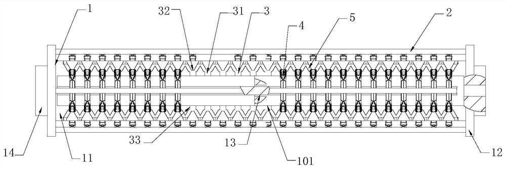
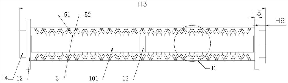
[0038]Such asFigures 1 to 7 As shown, the blade mounting base of the present embodiment includes a base 1 and a plurality of pressure rods 2, and the base 1 includes a square column 11, and each side of the square column 11 is provided with a support end seat 12, a square column 11. A set of positioning grooves 3 is provided, and each set of positioning grooves 3 includes a plurality of positioning grooves 3 arranged at intervals along the length direction of the square column 11, and the positioning groove 3 is used to mount the blade 4, and each set of positioning grooves 3 corresponds to a pressure rod 2, press The rod 2 is used to press the blade 4 in the positioning groove 3, and both ends of the pressure rod 2 are respectively provided on the support end seat 12 on both ends. The blade 4 is a non-porous installed cut cut slot blade.

[0039]The square column 11 of the present embodiment is square in a square in cross section. On the other hand, the square column 11 has four sides...

Embodiment 2

[0049]Such asFigure 8 As shown, the blade assembly clamp of the present embodiment includes a housing 6 and the blade mount base of the above-described Embodiment, and the base is provided on the strip rod 6, and both ends of the binder 6 from the base 1 support end. The seat 12 extends, and the binder 6 exits the dial 61 of the drive rod 6 rotating.

[0050]In this embodiment, the support end seat 12 is provided with a central bore, and the stripper 6 penetrates the center hole to achieve the blade mounting base to satisfy the blade coating process. The strip rod 6 rotates with the base 1 to ensure that the blades 4 are coated.

[0051]In the present embodiment, the strip rod 6 is a standard strip of the apparatus, and the outer diameter D1 of the strip rod 6 and the center hole in the support end seat 12, D1

Embodiment 3

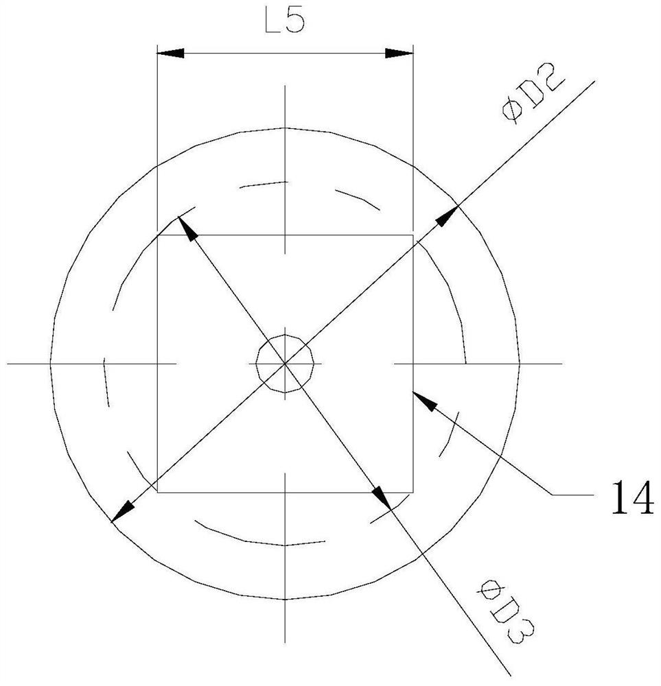
[0053]Such asFigure 9 to 11 As shown, the blade assembly clamp, including the tray frame 7 and the blade mount base of the above-described embodiment, and two support end seat 12 of each end, two of the pallets 14, the pallet frame 7 opposite A plurality of square grooves 71 are respectively provided on the border, and the square recess 71 on both frames corresponds to the two square grooves 71 corresponding to the two frames, and the two square recess 71 constitute a set of square grooves 71, the blade clamp A plurality of seats are arranged, and each blade mount base is engaged in each parallelete groove 71 through a square boss 14 at both ends.

[0054]When the blade mount base should be used in combination with the tray frame 7 during the cleaning process, the square groove 71 prevents the blade assembly base position from being shifted, and placed the tray frame 7 and the blade clip base on the cleaning. On the device, the blade cleaning process can be satisfied.

[0055]In this embo...


PUM


Abstract

The invention discloses a blade clamping base and a blade clamping fixture. The blade clamping base comprises a base body and a plurality of pressing rods, the base body comprises a square column, the two ends of the square column are each provided with a supporting end base, each side face of the square column is provided with a set of positioning grooves, each set of positioning grooves comprises a plurality of positioning groove bodies, the positioning grooves are used for installing blades, and each set of positioning grooves correspond to one pressing rod; and the pressing rods are used for pressing the blades in the positioning grooves, and the two ends of the pressing rods are arranged on the supporting end bases at the two ends correspondingly. The fixture comprises the blade clamping base, a material rod, a tray frame and a cover plate. According to the blade clamping base and the blade clamping fixture, the blades can be rapidly and accurately clamped through the positioning grooves, and the pressing rods act on the outer surfaces of the blades, so that it is guaranteed that the blades are stably and reliably clamped. The fixture can meet various production process requirements of sand blasting, cleaning and coating, the blades can be assembled and disassembled at a time, the blades are prevented from being assembled and disassembled repeatedly to meet different production process requirements, the production efficiency is effectively improved, the product percent of pass is increased, and the labor intensity and the machining cost are reduced.

Description

Technical field[0001]The present invention relates to cutting, and more particularly to a blade gear pedestal and a blade assembly clamp.Background technique[0002]Currently, in the metal turning industry, there is a type of blade for turning narrow grooves or cutting the workpiece, which we collectively refer to the blade. Such blade production requires blade sand blasting treatment, and then ultrasonic cleaning is cleaned into the coating process to complete the related process, and finally forms the finished product. Since this type of product is a non-porous blade, the prior art is multifaceted with a special jig, and is a special narrow groove plate for adapting to the sand blasting, cleaning, coating multi-channel processes. The general-purpose wide trough disk and the special blade magnetic coating clamp, the clamp is different, and it is not universal; the blade must be artificially unloaded in different processes to apply for processing equipment requirements for different p...

Claims


Application Information

Patent Timeline
Patent Type & Authority Applications(China)
IPC IPC(8): B24C1/02B24C9/00
CPCB24C1/02B24C9/00
Inventor 储永代赵丽丽张严王云志
Owner ZHUZHOU CEMENTED CARBIDE CUTTING TOOLS CO LTD
Why Eureka
Try Eureka