Pump head and container
A technology of pump head and axial movement, which is applied to the pump head that can quickly and large-capacity take out the contents. The container using this pump head is convenient in the field, and can solve the inconvenient disassembly and the inability to take out the viscous consistency. Problems such as liquid and airtightness are not easy to maintain
- Summary
- Abstract
- Description
- Claims
- Application Information
AI Technical Summary
Problems solved by technology
Method used
Image
Examples
Embodiment 1
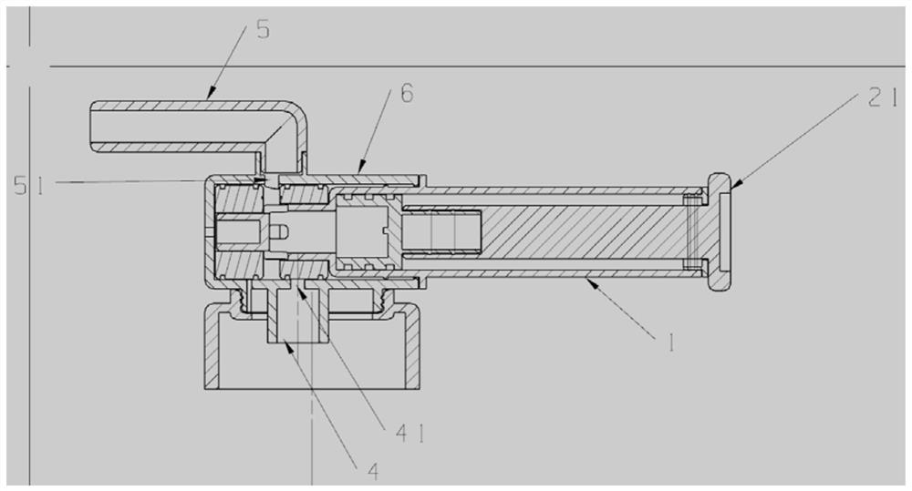
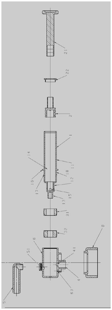
[0037] like figure 1 and figure 2 Shown is a pump head according to Embodiment 1 of the present invention. figure 1 is a sectional view of the pump head described in Example 1, figure 2 It is an exploded view of a sectional view of the pump head described in Example 1. The pump head includes an axial movement assembly 1 , a piston 2 , a sealing member 31 , a sealing member 32 , a suction channel 4 , an outflow channel 5 , a bracket 6 , a connecting rod 21 , a cover 22 , and a container cover 10 .
[0038] The axial movement assembly 1 includes a buffer liquid part 11, an opening part 12 and a closed end 13; one end of the opening part 12 is connected to the buffer liquid part 11, and the other end is connected to the closed end 13; the inner space of the buffer liquid part 11 and the opening part 12 is a liquid storage space 14. One end of the liquid storage space 14 is closed by the piston 2, and the other end is closed by the closed end 13; the opening 12 is provided wi...
Embodiment 2
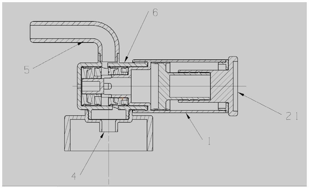
[0046] like image 3 Shown is a sectional view of a pump head according to Embodiment 2, Figure 4 for image 3 exploded view. The pump head includes an axial movement assembly 1 , a piston 2 , a sealing part 31 , a sealing part 32 , a liquid suction channel 4 , an outflow channel 5 , a bracket 6 , a connecting rod 21 and a cover 22 .
[0047] The axial movement assembly 1 includes a buffer liquid part 11, an opening part 12 and a closed end 13; one end of the opening part 12 is connected to the buffer liquid part 11, and the other end is connected to the closed end 13; the inner space of the buffer liquid part 11 and the opening part 12 is a liquid storage space 14. One end of the liquid storage space 14 is closed by the piston 2, and the other end is closed by the closed end 13; the opening 12 is provided with an opening 15, through which the liquid to be taken enters or leaves the liquid storage space 14 through the opening 15. A shoulder 16 and a chamfer 17 are provided...
Embodiment 3
[0054] like Figure 5 , Image 6 Shown is the pump head described in Embodiment 3. Figure 5 It is a sectional view and an exploded view of the pump head described in Embodiment 3, Image 6 It is a perspective view and an exploded view of the pump head described in Embodiment 3. The pump head includes an axial movement assembly 1 , a piston 2 , a sealing part 31 , a sealing part 32 , a suction channel 4 , an outflow channel 5 , a bracket 6 , and a connecting cover 21 .
[0055] The axial movement assembly 1 includes a buffer liquid part 11, an opening part 12 and a closed end 13; one end of the opening part 12 is connected to the buffer liquid part 11, and the other end is connected to the closed end 13; the inner space of the buffer liquid part 11 and the opening part 12 is a liquid storage space 14. One end of the liquid storage space 14 is closed by the piston 2, and the other end is closed by the closed end 13; the opening 12 is provided with an opening 15, through whic...
PUM
 Abstract
Description
Claims
Application Information
 - R&D
- Intellectual Property
- Life Sciences
- Materials
- Tech Scout
- Unparalleled Data Quality
- Higher Quality Content
- 60% Fewer Hallucinations
Browse by: Latest US Patents, China's latest patents, Technical Efficacy Thesaurus, Application Domain, Technology Topic, Popular Technical Reports.
© 2025 PatSnap. All rights reserved.Legal|Privacy policy|Modern Slavery Act Transparency Statement|Sitemap|About US| Contact US: help@patsnap.com


