
Catalytic reactor with cooling device provided with tangential injection of cooling fluid

A technology for catalytic reactors and cooling fluids, applied in chemical/physical/physicochemical nozzle reactors, chemical instruments and methods, catalyst activation/preparation, etc., can solve problems such as difficulty in installing and maintaining reactors, bulky injection tubes, etc. , to achieve the effect of increased volume, easy mechanical assembly, and moderate cost

Active Publication Date: 2018-01-23
INST FR DU PETROLE
View PDF17 Cites 0 Cited by
  • Summary
  • Abstract
  • Description
  • Claims
  • Application Information

AI Technical Summary

Problems solved by technology

However, injection tubes are bulky and mechanically difficult to install and maintain in the reactor

Method used


Image

  • Catalytic reactor with cooling device provided with tangential injection of cooling fluid
  • Catalytic reactor with cooling device provided with tangential injection of cooling fluid
  • Catalytic reactor with cooling device provided with tangential injection of cooling fluid

Examples


Embodiment Construction

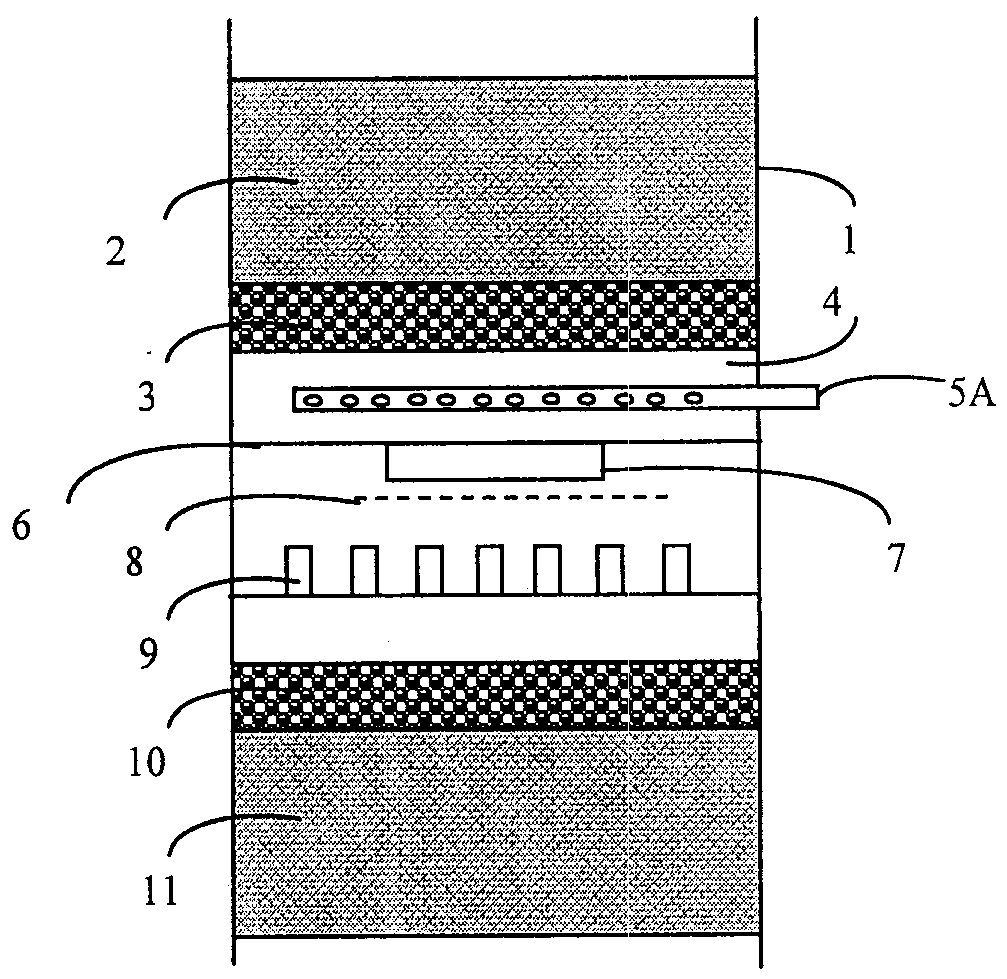
[0028] figure 1 A portion of a reactor in which a hydrotreating reaction is performed is presented. The reactor consists of a shell 1 comprising at least one bed 2 of solid catalyst. The housing 1 may be in the shape of a cylinder closed at its ends. Generally, the axis of the cylinder is oriented in a vertical direction. For example, the cylinder may have a diameter in the range of 1 meter to 10 meters and a height in the range of 3 meters to 20 meters. The upper part of the reactor is supplied with a reaction fluid consisting of gas and liquid, for example, a feed of liquid hydrocarbons and gaseous hydrogen. The reaction fluid flows in a downward vertical direction in the housing 1 , in particular under the force of gravity. In other words, gas and liquid flow as co-currents from the top to the bottom of the reactor. The reaction between the reactants is catalyzed by a solid catalyst, which may be in the form of extrudates or beads placed between two screens, so that a ...


PUM

PropertyMeasurementUnit
lengthaaaaaaaaaa
diameteraaaaaaaaaa

Abstract

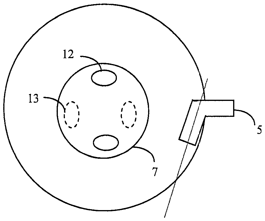
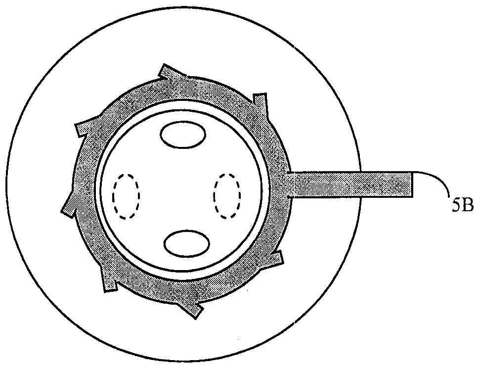
The invention relates to a catalytic reactor with a cooling device provided with tangential injection of cooling fluid. In particular, the catalytic reactor consists of a shell (1) comprising at least two solid catalyst beds (2, 11) separated by a collecting plate (6) cooperating with a quench box (7). The reactor comprises spray nozzles (5) arranged in the collection zone (4) above the collection plate (6). The spray nozzle (5) consists of a pipe comprising a single orifice at the end of the pipe and the maximum distance between the housing and the nozzle is in the range of 0cm to 40cm. The end of the spray nozzle (5) consists of a tubular section configured so that the fluid is sprayed into the collection area (4) in a substantially horizontal direction and opposite to the wall of the housing (1) at said tubular section The tangential directions form an angle in the range -10° to +10°.

Description

technical field [0001] The present invention relates to the field of fixed bed catalytic reactors for hydrocarbon feed hydroprocessing operations. The present invention describes a system for injecting cooling fluid into a reactor. Background technique [0002] Catalytic reactors are used in particular in the oil and petrochemical industries to treat hydrocarbon effluents by hydrotreating. Such reactions react carbon-containing compounds with hydrogen in hydrogenation reactions, hydrodesulfurization reactions, hydrodenitrogenation reactions, hydrocracking reactions, or hydrodearomatization reactions. [0003] The catalytic reactor is generally constituted by a cylindrical shell containing one or more catalytic beds, ie beds of solids, for example solids having an extruded or spherical shape, for catalyzing the hydroprocessing reaction. The reactor is fed from the top with a reaction fluid consisting of hydrocarbon effluent and hydrogen. [0004] The exothermic nature of t...

Claims


Application Information

Patent Timeline
Patent Type & Authority Patents(China)
IPC IPC(8): B01J8/04
CPCB01J8/0453B01J8/0492B01J8/0496B01J2208/00362B01J2208/00371B01J2208/025B01J2219/00024C10G49/002B01J19/26B01J37/00B01J8/04
Inventor F.奥吉耶C.布瓦耶D.斯韦齐亚
Owner INST FR DU PETROLE
Learn More