
A macro-channel liquid-cooled high-power semiconductor laser module and device

A laser and macro channel technology, applied in semiconductor lasers, lasers, laser parts, etc., can solve problems such as the expansion of the number of bars that are difficult to assemble and spliced, the lack of overall strength and rigidity of the heat sink, and the impact on the quality of the package. Good structure, improved heat dissipation effect, convenient mechanical assembly effect

Active Publication Date: 2019-01-08
FOCUSLIGHT TECH
View PDF15 Cites 0 Cited by
  • Summary
  • Abstract
  • Description
  • Claims
  • Application Information

AI Technical Summary

Problems solved by technology

This kind of packaging structure can achieve higher power output through the superposition of heat sinks, but this packaging method has the following disadvantages: first, the microchannel is easy to be blocked because of the narrow water channel; second, the heat sink itself is charged, so it must be Deionized water is used for cooling, and there are high requirements for ion concentration; third, the high-speed water flow in the micro-channel will cause erosion of the channel and lead to product failure; fourth, the overall strength and stiffness of the micro-channel heat sink are lacking , easy to bend and deform during assembly and manufacturing, thus affecting the quality of the package
Based on each product of this heat sink structure, it is difficult to assemble and splice to achieve the expansion of the number of bars
When more bars are needed, only bottom heat sinks of different sizes can be made for matching and adaptation

Method used


Image

  • A macro-channel liquid-cooled high-power semiconductor laser module and device
  • A macro-channel liquid-cooled high-power semiconductor laser module and device
  • A macro-channel liquid-cooled high-power semiconductor laser module and device

Examples


Embodiment Construction

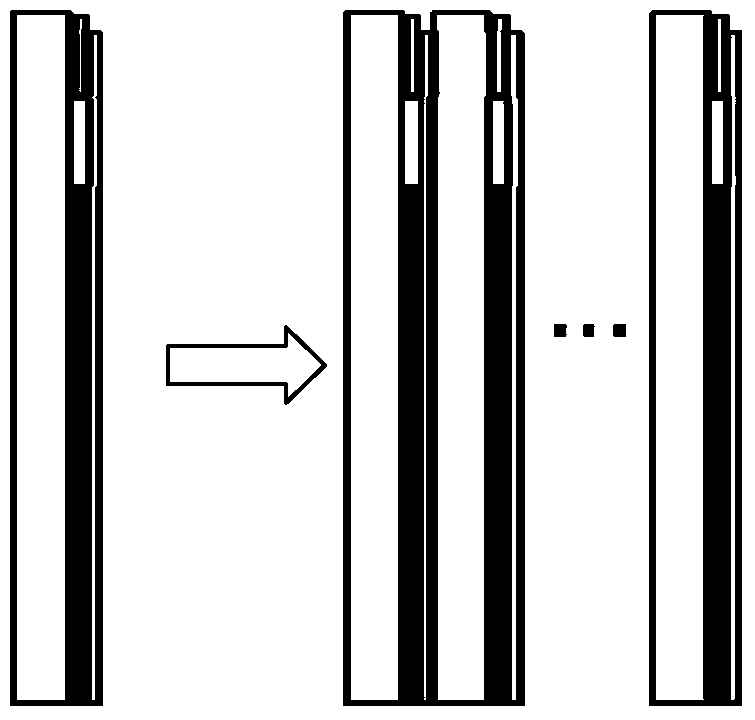
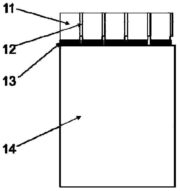
[0039] Such as image 3 , 4 As shown, the laser chip 12 is assembled on a substrate 11 of a conductive material with high thermal conductivity and CTE matching, and the substrate material is a diamond-copper alloy. The substrate mounted with the laser chip is assembled to the heat sink 14 through the insulating block 13 with high thermal conductivity to form a laser module. A water inlet and a water outlet parallel to each other are opened through the side of the heat sink, and a liquid cooling circuit of a macro channel is arranged inside the heat sink. Multiple laser modules can be "seamlessly" connected through the sealing ring, share the water inlet 15 and the water outlet 16, and realize expansion, such as Figure 5 shown.

[0040] The heat sink is specifically composed of multi-layer water-passing plates, and the flow direction between adjacent two layers is opposite to achieve uniformity of heat dissipation on the laser mounting surface. The heat sink of the heat si...


PUM


Abstract

The invention proposes a macro-channel liquid-cooling high-power semiconductor laser module and an apparatus formed by combining multiple modules. A unique heat sink design is combined with a chip set, so that the laser module is good in structural property and high in heat dissipation efficiency. The macro-channel liquid-cooling high-power semiconductor laser module comprises a heat sink and the chip set, wherein each laser chip of the chip set is bonded on a corresponding heat-conducting and conductive substrate; the laser chips and the chip substrates are stacked in sequence and form electric connection; the substrates are mounted on the same heat sink through insulation layers; and in the stacking direction of the laser chips and the substrates, a water inlet and a water outlet parallel to each other are formed in the side surfaces of the heat sink perpendicular to a mounting surface of the chip set in a run-through manner, and a liquid cooling loop of a macro-channel is arranged in the heat sink. The multiple modules can be conveniently and mechanically assembled and maintained to realize elastic power extension; and each module serves as a functional unit and can truly perform testing, aging and screening in a working state to realize the optimization performance of a final product.

Description

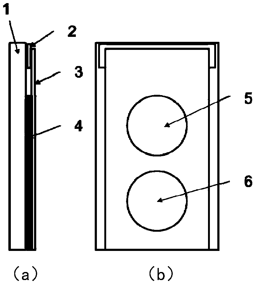
technical field [0001] The invention relates to a packaging structure of a high-power semiconductor laser. Background technique [0002] The heat dissipation design of high-power semiconductor lasers is one of the core contents of packaging. Current high-power semiconductor lasers are usually packaged in the following ways: [0003] a) if figure 1 , figure 2 As shown, the laser bar is directly bonded to the heat sink, which adopts a microchannel-based structure heat sink. This kind of packaging structure can achieve higher power output through the superposition of heat sinks, but this packaging method has the following disadvantages: first, the microchannel is easy to be blocked because of the narrow water channel; second, the heat sink itself is charged, so it must be Deionized water is used for cooling, and there are high requirements for ion concentration; third, the high-speed water flow in the micro-channel will cause erosion of the channel and lead to product fail...

Claims


Application Information

Patent Timeline
Patent Type & Authority Patents(China)
IPC IPC(8): H01S5/024
CPCH01S5/02423H01S5/02438
Inventor 刘兴胜蔡万绍陶春华邢卓梁雪杰
Owner FOCUSLIGHT TECH
Learn More