Electro-hydraulic compound control underground decoding device and decoding method thereof

An electro-hydraulic composite and decoding device technology, which is applied to valve devices of wellbore/well, earthwork drilling, wellbore/well components, etc. The existence of small motors and electronic components, the effect of improving the efficiency of layer recognition and improving process reliability

Active Publication Date: 2021-04-23
CHINA NAT OFFSHORE OIL CORP +1
View PDF8 Cites 2 Cited by
  • Summary
  • Abstract
  • Description
  • Claims
  • Application Information

AI Technical Summary

Problems solved by technology

[0003] At home and abroad, a lot of related research has been done on the layering control of oil-water wells. In the early stage, the mechanical sliding sleeve switch method was used to switch the mechanical sliding sleeve through steel wire operation to realize the opening and closing of downhole layers. The problem with this method is that for highly deviated wells, For horizontal wells, the steel wire operation cannot be adjusted, and the construction process is complicated through the steel wire cable control method, which affects the normal production of oil and water wells and the control efficiency is low
This method can switch and control the downhole layers without affecting normal production. Compared with wire and cable operations, the control efficiency has been greatly improved. When there are many layers of oil and water wells, the number of hydraulic control pipelines is large. , causing the overall process availability to be limited. Although a hydraulic decoding method and device for downhole layer selection in intelligent wells (patent number: 2010105826522) appeared later, it uses hydraulic decoding, and the decoding efficiency is low. At the same time, there is a delay in the transmission of the hydraulic control fluid. problem, resulting in high decoding failure rate and affecting downhole control accuracy; with the gradual maturity of electronic technology, an electronically controlled intelligent well completion measurement and adjustment system and method (patent number: 2010105826522) gradually emerged. This system uses a cable to realize downhole electronic control. The adjustment of the sliding sleeve is easy to operate and the adjustment efficiency is high, but the problem is that the reliability of electronic components is limited in the high temperature and high pressure environment underground, resulting in poor reliability of the overall process

Method used


Image

  • Electro-hydraulic compound control underground decoding device and decoding method thereof
  • Electro-hydraulic compound control underground decoding device and decoding method thereof
  • Electro-hydraulic compound control underground decoding device and decoding method thereof

Examples


Embodiment 1

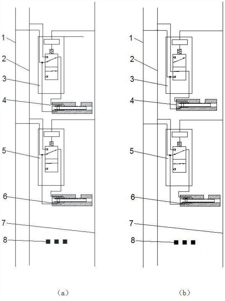
[0032] An electro-hydraulic composite control downhole decoding device, comprising a first hydraulic control pipeline 1, a second hydraulic control pipeline 2, an electro-hydraulic composite control device, a signal control cable 7 and a lower electro-hydraulic composite control system 8,

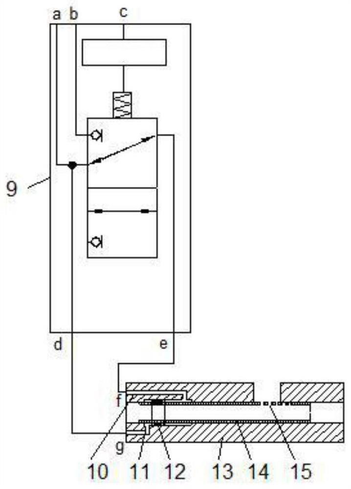
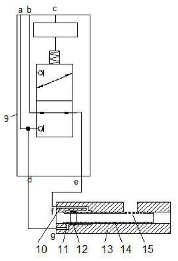
[0033]The electro-hydraulic compound control device includes an electro-hydraulic compound control decoder and a hydraulic control sliding sleeve, and the electro-hydraulic compound control decoder includes a decoder shell 9, a first electro-hydraulic compound control pipeline 16, an electro-hydraulic compound control circuit system 17, a second electric Liquid compound control pipeline 18, two-position three-way solenoid valve 19 and internal signal control cable 20,

[0034] When the electro-hydraulic composite control decoder is in the closed state, the first hydraulic control pipeline 1 is connected to the hole a on the decoder casing 9, and the a hole on the decoder casing 9 is respecti...

Embodiment 2

[0039] On the basis of Embodiment 1, the hydraulic control sliding sleeve includes an upper liquid inlet hole 10, a lower liquid inlet hole 11, a piston 12, a casing 13, a central tube 14, and a liquid outlet hole 15. On the side wall of the casing 13, there are The liquid guide hole that runs through the side wall of the shell 13, the central tube 14 is sleeved in the shell 13, and the liquid outlet hole 15 that runs through the side wall of the central tube 14 is uniformly opened on the lower side wall of the central tube 14 opposite the liquid guide hole , at the head end of the casing 13, there are respectively an upper lifting liquid inlet 10 and a lower lowering liquid inlet 11 through the side wall of the outer casing 13, and the upper lifting liquid inlet 10 and the lower lowering liquid inlet 11 are controlled by the hydraulic pressure and the piston 12. Lifting and lowering of the pipe 14 to realize the adjustment of the horizon.

Embodiment 3

[0041] On the basis of the second embodiment, adjacent electro-hydraulic control devices are separated and hermetically sealed by packers.

[0042] The number of electro-hydraulic composite control devices is 2-12.

[0043] In the initial state, the electro-hydraulic compound control decoder is closed.

[0044] The signal control cable 7 is connected with the ground control equipment, so as to realize the purpose of controlling the downhole electro-hydraulic composite decoder by using the ground control equipment.


PUM


Abstract

The invention provides an electro-hydraulic compound control underground decoding device and a decoding method thereof. A first hydraulic control pipeline and a second hydraulic control pipeline are respectively connected with an electro-hydraulic compound control device and are connected with ground control equipment through a signal control cable of an electro-hydraulic compound control decoder; a lower electro-hydraulic compound control system is arranged below the electro-hydraulic compound control device located at the bottommost end of a well. Horizon identification is realized by utilizing a circuit system, so that the action of a two-position three-way electromagnetic valve is realized, pressure liquid is guided, the horizon identification efficiency is improved, the problem of delay of a hydraulic decoding system is solved, and the identification precision is improved; and a hydraulic control sliding sleeve is driven through the two hydraulic control pipelines, and compared with a full electric control mode, the number of motors and electronic components is reduced and the driving torque is increased, so therefore the overall process reliability is improved.

Description

technical field [0001] The invention relates to the technical field of oil and gas exploration and development, and more specifically relates to an electro-hydraulic composite control downhole decoding device and a decoding method thereof. Background technique [0002] In order to carry out efficient oilfield development and production, multi-layer oil recovery and water injection are currently used. With the deepening of development, the number of oil well layers is large, the pressure difference between layers is large, and the contradiction between layers is prominent, resulting in serious edge and bottom water intrusion in some layers. This results in an increase in the water content of the well. Therefore, in order to achieve the purpose of stabilizing oil, controlling water, increasing production and improving efficiency, it is necessary to effectively control the development layer of the oil well, and realize the adjustment of interlayer pressure through the throttlin...

Claims


Application Information

Patent Timeline
Patent Type & Authority Applications(China)
IPC IPC(8): E21B34/14E21B34/16
CPCE21B34/14E21B34/16
Inventor 杨万有张凤辉薛德栋晁圣棋黄小凤张玺亮沙吉乐缪油花
Owner CHINA NAT OFFSHORE OIL CORP
Why Eureka
Try Eureka