An electro-hydraulic composite control downhole decoding device and its decoding method
An electro-hydraulic composite and decoding device technology, which is applied to wellbore/well valve devices, earthwork drilling and production, wellbore/well components, etc., can solve problems such as poor process reliability, affecting downhole control accuracy, delay, etc., and achieve reduction The existence of small motors and electronic components, the improvement of layer recognition efficiency, and the effect of improving process reliability
- Summary
- Abstract
- Description
- Claims
- Application Information
AI Technical Summary
Problems solved by technology
Method used
Image
Examples
Embodiment 1
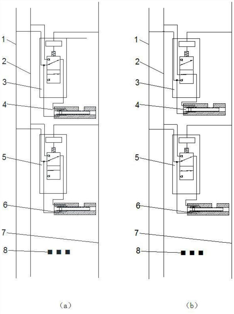
[0031] An electro-hydraulic composite control downhole decoding device includes a first hydraulic control pipeline 1 , a second hydraulic control pipeline 2 , an electro-hydraulic composite control device, a signal control cable 7 and a lower electro-hydraulic composite control system 8 .
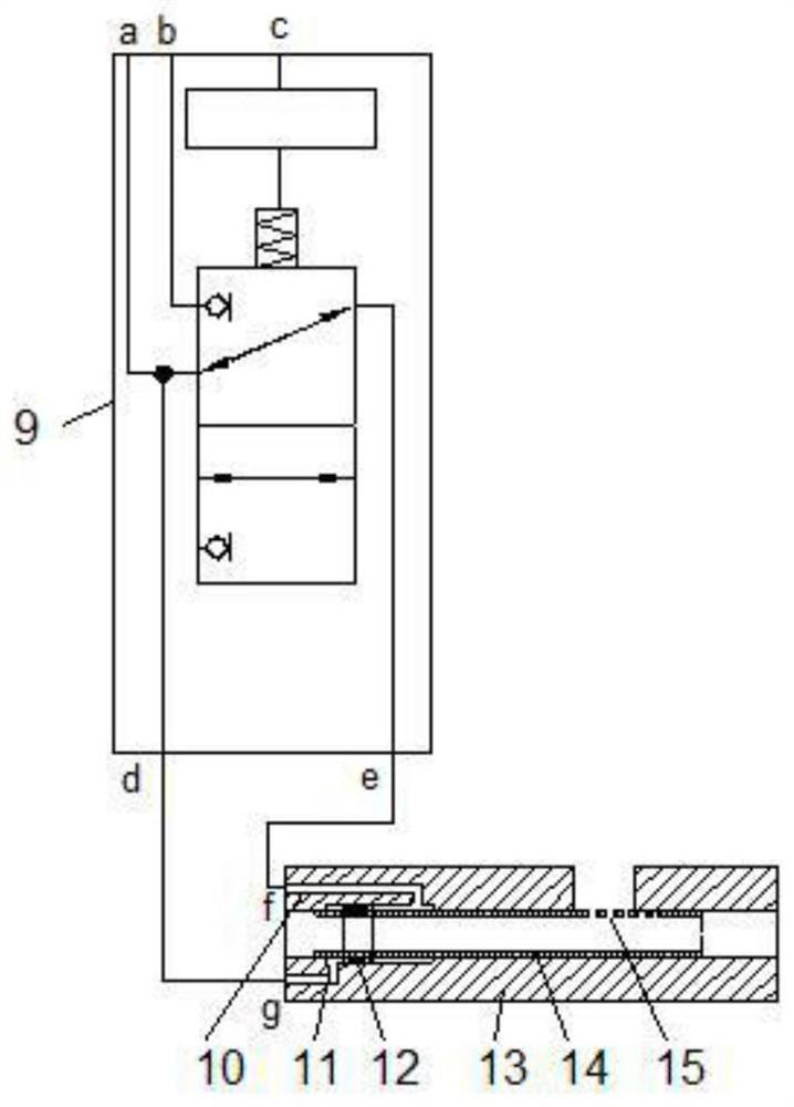
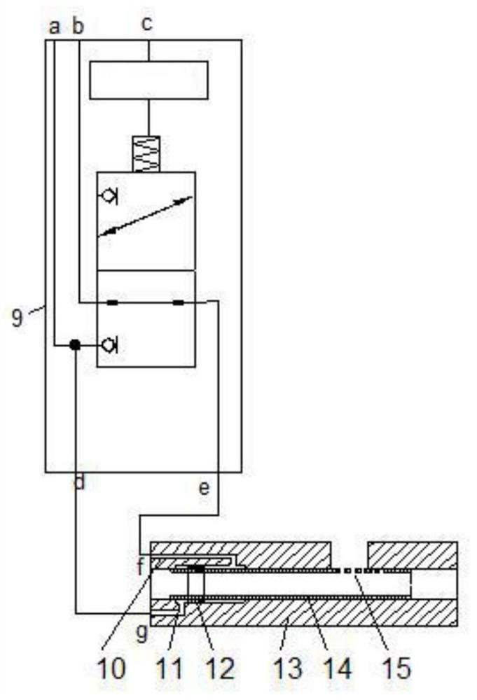
[0032]The electro-hydraulic composite control device includes an electro-hydraulic composite control decoder and a hydraulically controlled sliding sleeve. The electro-hydraulic composite control decoder includes a decoder shell 9, a first electro-hydraulic composite control pipeline 16, an electro-hydraulic composite control circuit system 17, and a second electro-hydraulic composite control circuit system. Hydraulic composite control pipeline 18 , two-position three-way solenoid valve 19 and internal signal control cable 20 .
[0033] When the electro-hydraulic composite control decoder is in the closed state, the first hydraulic control pipeline 1 is connected to the a hole on the decoder...
Embodiment 2
[0038] On the basis of the first embodiment, the hydraulic control sliding sleeve includes an upward liquid inlet hole 10 , a lower liquid inlet hole 11 , a piston 12 , a casing 13 , a central pipe 14 and a liquid outlet hole 15 , and the side wall of the casing 13 is provided with The liquid guide hole penetrating the side wall of the casing 13 is sleeved with the central pipe 14 in the casing 13, and the liquid outlet hole 15 penetrating the side wall of the central pipe 14 is uniformly opened at the lower side wall of the central pipe 14 opposite to the liquid guide hole , the head end of the casing 13 is respectively provided with an upward lifting liquid inlet hole 10 and a lower liquid feeding hole 11 penetrating the side wall of the casing 13, and the upper lifting liquid feeding hole 10 and the lower liquid feeding hole 11 are controlled by the hydraulic pressure and the piston 12. The lifting and lowering of the pipe 14 can realize the adjustment of the level.
Embodiment 3
[0040] On the basis of the second embodiment, the adjacent electro-hydraulic composite control devices are separated and sealed by a packer.
[0041] The number of electro-hydraulic composite control devices is 2-12.
[0042] In the initial state, the electro-hydraulic composite control decoder is turned off.
[0043] The signal control cable 7 is connected with the ground control equipment, so as to realize the purpose of using the ground control equipment to control the downhole electro-hydraulic composite decoder.
PUM
 Abstract
Description
Claims
Application Information
 - R&D
- Intellectual Property
- Life Sciences
- Materials
- Tech Scout
- Unparalleled Data Quality
- Higher Quality Content
- 60% Fewer Hallucinations
Browse by: Latest US Patents, China's latest patents, Technical Efficacy Thesaurus, Application Domain, Technology Topic, Popular Technical Reports.
© 2025 PatSnap. All rights reserved.Legal|Privacy policy|Modern Slavery Act Transparency Statement|Sitemap|About US| Contact US: help@patsnap.com


