Bunch-by-bunch three-dimensional position measurement system and measurement method

A three-dimensional position and measurement system technology, applied in the measurement of electrical variables, measurement devices, phase angle between voltage and current, etc., can solve problems such as peak point offset, measurement error, sampling point phase offset, etc. The effect of removing clock jitter and phase oscillation, ensuring data consistency, and avoiding measurement errors

Active Publication Date: 2021-04-23
SHANGHAI ADVANCED RES INST CHINESE ACADEMY OF SCI
View PDF9 Cites 0 Cited by
  • Summary
  • Abstract
  • Description
  • Claims
  • Application Information

AI Technical Summary

Problems solved by technology

[0005] The signal sampling points of the above two systems need to be controlled by the external clock of the acquisition system. In the lateral position system, it is necessary to ensure that the sampling point of each electrode signal is located at the peak point, but the jitter of the external clock and the oscillation of the bunch phase will both The offset of the peak point sampling, resulting in measurement error
In the longitudinal phase system, it is necessary to ensure that the two sampling points with a fixed phase difference (T) are located in the linear region of the rising edge of the signal, but the jitter of the external clock will also cause the phase shift of the sampling points, resulting in measurement errors
Moreover, since the induced voltage signal obtained by each electrode is a sinusoidal signal, and the zero-crossing point of the sinusoidal signal is approximately linear rather than a normal linear relationship, so there is a deviation in the phase of the zero-crossing point obtained by fitting
In addition, this measurement method needs to use more experimental instruments, and has high requirements for simultaneous sampling of the three-dimensional position measurement of each cluster

Method used


Image

  • Bunch-by-bunch three-dimensional position measurement system and measurement method
  • Bunch-by-bunch three-dimensional position measurement system and measurement method
  • Bunch-by-bunch three-dimensional position measurement system and measurement method

Examples


Embodiment Construction

[0035] Below in conjunction with the drawings, preferred embodiments of the present invention are given and described in detail.

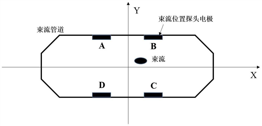
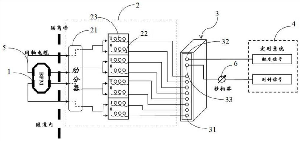
[0036] Such as figure 1 As shown, the beam-by-beam three-dimensional position measurement system of a preferred embodiment of the present invention includes N button-type beam current position probes 1 installed on the beam pipeline in the tunnel, a phase separation sampling circuit 2, and a data acquisition system 3 and a timing system 4, wherein each beam position probe 1 is connected to the phase-separated sampling circuit 2 through a coaxial cable 5, and the coaxial cable 5 leads out the voltage signal output by the beam position probe 1 and inputs it to the phase-separated sampling circuit 2. The phase-splitting sampling circuit 2 is electrically connected to the data acquisition system 3 , and the data acquisition system 3 is electrically connected to the timing system 4 .

[0037] The phase-splitting sampling circuit 2 includes N one-to-two...


PUM


Abstract

The invention relates to a bunch-by-bunch three-dimensional position measurement system which comprises a plurality of button type beam position probes, each beam position probe is connected with a split-phase sampling circuit through a coaxial cable, the split-phase sampling circuit is electrically connected with a data acquisition system, and the data acquisition system is electrically connected with a timing system. According to the bunch-by-bunch three-dimensional position measurement system, the measurement time is saved, and the data consistency is ensured. The invention further relates to a bunch-by-bunch three-dimensional position measurement method, the split-phase sampling technology is adopted, signal amplitude and phase information are obtained by establishing a lookup table for mode matching, measurement errors caused by linear fitting are avoided, influences caused by clock jitter and phase oscillation are effectively removed, and the precision of extracting the three-dimensional position information of the bunch-by-bunch group is improved.

Description

technical field [0001] The invention relates to a particle accelerator physical beam diagnosis technology, in particular to a beam-by-beam three-dimensional position measurement system and a measurement method. Background technique [0002] For multi-electrode beam position detectors, the figure 1 The button-type beam position detector (probe) (BPM) with four electrodes A, B, C, and D on the electron storage ring shown is taken as an example, in order to obtain three-dimensional position information (lateral position, Longitudinal phase), the current measurement method is to first process the signals output by the four electrodes separately, and then use the data acquisition board to sample. Specifically, the measurement principle as figure 2 As shown, a set of horizontal position acquisition system is set up first, and the peak points of the four electrode signals are respectively obtained by using the peak detection technology, and the position information is extracted ...

Claims


Application Information

Patent Timeline
Patent Type & Authority Applications(China)
IPC IPC(8): G01R25/00
CPCG01R25/00Y02E30/30
Inventor 周逸媚冷用斌高波
Owner SHANGHAI ADVANCED RES INST CHINESE ACADEMY OF SCI
Why Eureka
Try Eureka