Light guide assembly of light-emitting semiconductor
A technology for light-emitting semiconductors and light-guiding components, which is applied in the directions of light guides, optical components, optics, etc., can solve the problems of light intensity adjustment of incapable light-emitting semiconductors, and achieve the effect of improving sealing and waterproof performance and facilitating disassembly and assembly.
- Summary
- Abstract
- Description
- Claims
- Application Information
AI Technical Summary
Problems solved by technology
Method used
Image
Examples
Embodiment 1
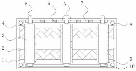
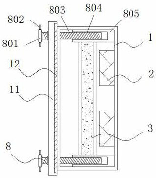
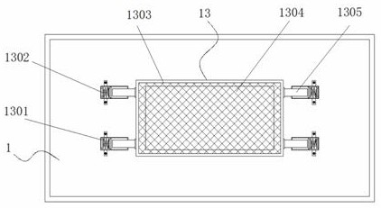
[0035] Example 1: See Figure 1-6 , a light guide assembly for light-emitting semiconductors, including a box body 1 and a light guide plate 2, two sets of light guide plates 2 are fixedly connected inside the box body 1, three sets of reflectors 3 are arranged on the top of the light guide plate 2, and the outside of the reflector 3 A reflective structure 4 is provided, and the four corners inside the box body 1 are fixedly connected with a disassembly structure 8. One end of the box body 1 is provided with a cover body 11, and one end of the cover body 11 is provided with a sealing structure 12. The other end of the box body 1 One end is fixedly connected with a dust-proof structure 13, and the inside of the box body 1 is provided with an adjustment structure;
[0036] see Figure 1-6, a light-emitting semiconductor light guide assembly also includes an adjustment structure, the adjustment structure includes an adjustment plate 7, the adjustment plate 7 is fixedly connected...
Embodiment 2
[0040] Embodiment 2: The reflective structure 4 is made up of reflective surface 401, first reflective sheet 402, second reflective sheet 403 and third reflective sheet 404, reflective surface 401 is fixedly connected to the outside of reflector 3, and one side of reflective surface 401 is fixed A first reflection sheet 402 is connected, two sets of second reflection sheets 403 are fixedly connected to the top and bottom of the reflection surface 401, and a third reflection sheet 404 is fixedly connected to the other side of the reflection surface 401;
[0041] The first reflector 402 is provided with two groups and is symmetrically distributed with respect to the vertical centerline of the reflector 3;
[0042] Specifically, such as figure 1 and Figure 5 As shown, a reflective surface 401 for reflecting light is installed on the outside of the reflector 3, and a first reflective sheet 402, a second reflective sheet 403, and a third reflective sheet 404 that can enhance the ...
Embodiment 3
[0043] Embodiment 3: The assembly and disassembly structure 8 is composed of a turntable 801, a rotating rod 802, a threaded rod 803, a connecting groove 804 and a connecting column 805. The connecting column 805 is fixedly connected to the four corners inside the box body 1, and the inside of the connecting column 805 A connecting groove 804 is provided, and a threaded rod 803 is arranged inside the connecting groove 804. The top of the threaded rod 803 is fixedly connected to a turntable 801, and two sets of rotating rods 802 are fixedly connected to both sides of the turntable 801;
[0044] The outer width of the threaded rod 803 is smaller than the inner width of the connection groove 804, and the threads on the outside of the threaded rod 803 are engaged with the internal threads of the connection groove 804;
[0045] Specifically, such as figure 1 and figure 2 As shown, the existing light guide assembly is small in size, which leads to inconvenient disassembly and asse...
PUM
 Abstract
Description
Claims
Application Information
 - R&D
- Intellectual Property
- Life Sciences
- Materials
- Tech Scout
- Unparalleled Data Quality
- Higher Quality Content
- 60% Fewer Hallucinations
Browse by: Latest US Patents, China's latest patents, Technical Efficacy Thesaurus, Application Domain, Technology Topic, Popular Technical Reports.
© 2025 PatSnap. All rights reserved.Legal|Privacy policy|Modern Slavery Act Transparency Statement|Sitemap|About US| Contact US: help@patsnap.com


