Lightning protection and energy storage device for high-rise building

A technology for energy storage devices and high-rise buildings, applied in circuit devices, sustainable buildings, corona discharge devices, etc., can solve the problems that the lightning protection device cannot be adjusted, does not have, and the lightning protection range is small, so as to increase the lightning protection range, Improve the function and increase the effect of lightning protection range

Active Publication Date: 2021-04-23
蔡永祥
View PDF7 Cites 4 Cited by
  • Summary
  • Abstract
  • Description
  • Claims
  • Application Information

AI Technical Summary

Problems solved by technology

[0003] Therefore, lightning protection measures for high-rise buildings are essential, and the general lightning protection device cannot be adjusted when used, and the effective lightning protection range is o...

Method used


Image

  • Lightning protection and energy storage device for high-rise building
  • Lightning protection and energy storage device for high-rise building
  • Lightning protection and energy storage device for high-rise building

Examples


Embodiment 1

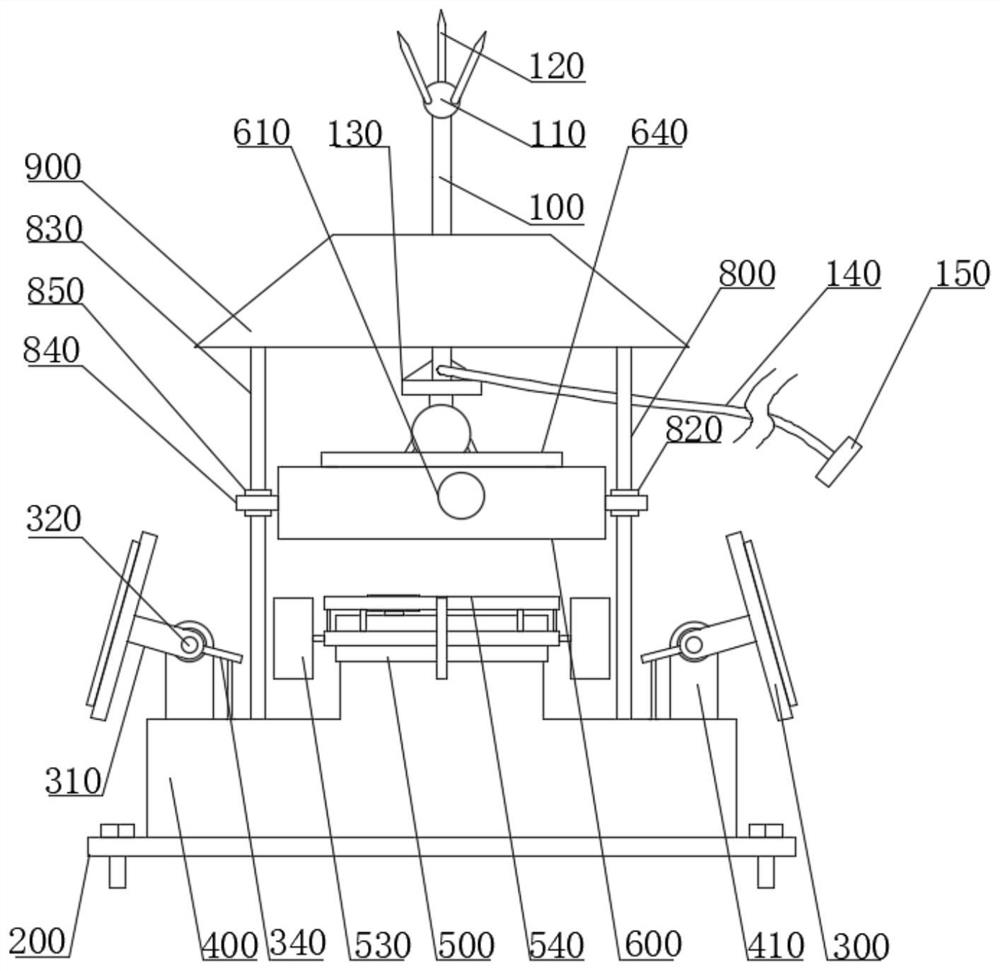
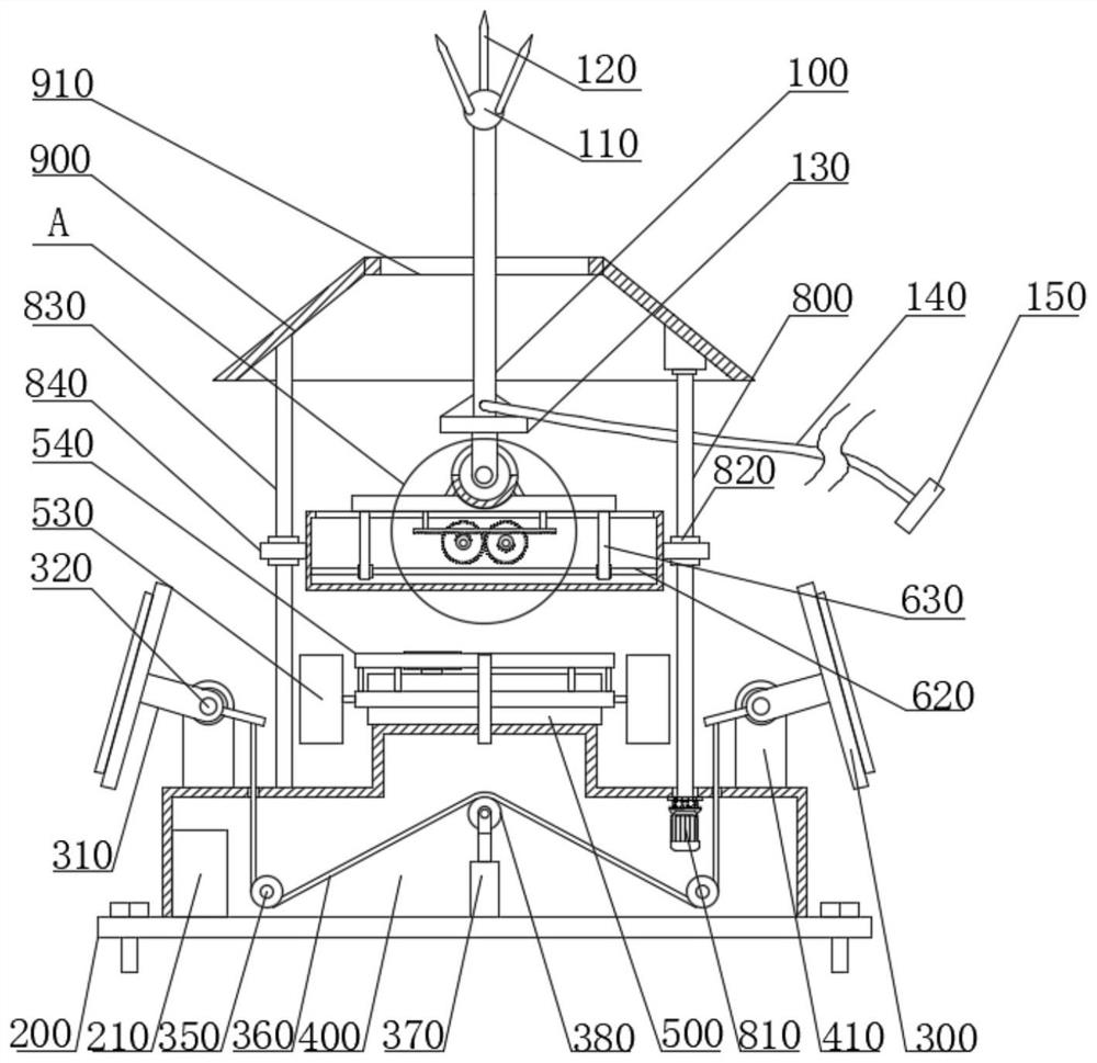
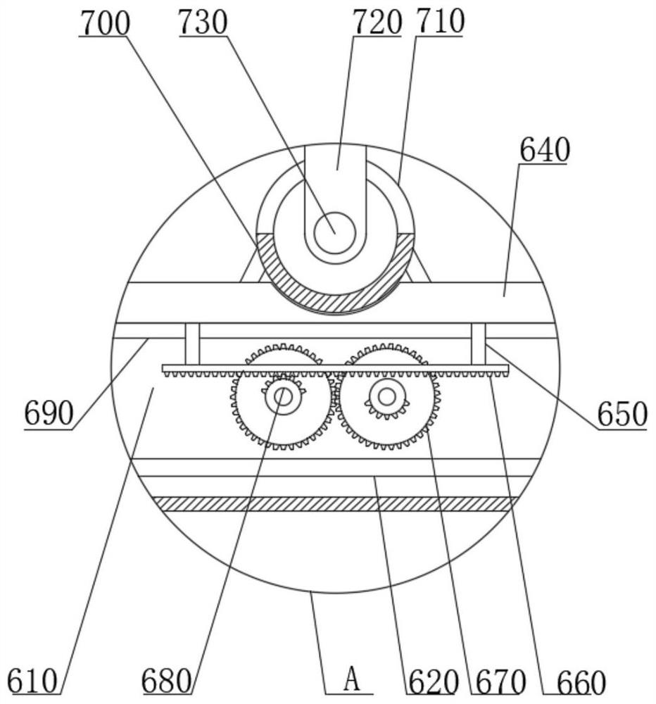
[0028] see figure 1 , figure 2 , image 3 , Figure 5 with Image 6 , a lightning protection energy storage device for high-rise buildings, a lightning protection energy storage device for high-rise buildings, comprising a first lightning rod 100; a lifting mechanism; a base 200; and a third housing 600; the top of the first lightning rod 100 A sphere 110 is fixedly connected, and the top of the sphere 110 is fixedly connected with several second lightning rods 120; one end of the first lightning rod 100 is electrically connected to the grounding body 150 through a wire 140; the bottom of the first lightning rod 100 The end is fixedly connected with the fixed seat 130; the top of the base 200 is fixedly connected with the first housing 400, and the top of the first housing 400 is connected with the third housing 600 through the lifting mechanism; the third housing The top of the 600 is provided with a guide chute 690; two driving gears 670 are installed side by side in th...

Embodiment 2

[0046] As a preferred solution of Embodiment 1, please refer to figure 1 , figure 2 , Figure 4 , Figure 7 with Figure 8 , the top of the first housing 400 is also fixedly connected with the second housing 500, and the annular side of the second housing 500 is provided with a limit slide 560, and the outer end of the second housing 500 is provided with Turning circle 510, and the inner wall of the turning circle 510 is fixedly connected with a limit slide bar 570, and the limit slide bar 570 is slidably connected to a limit chute 560, and the annular side of the turn circle 510 is evenly and fixedly connected with several fan blades 530 The top of the rotating circle 510 is fixedly connected with a ring gear 540, and the second casing 500 is also fixedly connected with a generator 580, and the output shaft of the generator 580 passes through the second casing 500 and connects with the power gear 590 Fixedly connected, the power gear 590 meshes with the ring gear 540;

...

Embodiment 3

[0054] As a preferred solution of Embodiment 1 or Embodiment 2, please refer to figure 1 with figure 2 , the lifting mechanism includes a third motor 810, a threaded rod 800, a nut block 820 and a limit rod 830, the first housing 400 is fixedly connected with a third motor 810, the output shaft of the third motor 810 passes through After passing through the first housing 400, it is fixedly connected with the threaded rod 800. The top of the first housing 400 is also fixedly connected with the limit rod 830. Both ends of the third housing 600 are fixedly connected with fixed blocks 840. A fixed sleeve 850 and a nut block 820 are respectively fixedly embedded in each of the fixed blocks 840, and the fixed sleeve 850 is slidably connected to the limit rod 830; the nut block 820 is threadedly connected to the threaded rod 800;

[0055] Wherein, the limit rod 830 acts as a limit guide;

[0056] Wherein, the third motor 810 drives the threaded rod 800 to rotate;

[0057] The top...


PUM


Abstract

The invention relates to a lightning protection and energy storage device for a high-rise building. The lightning protection and energy storage device comprises a first lightning rod, a lifting mechanism, a base, and a third shell. The top end of the first lightning rod is fixedly connected with a sphere, and the top end of the sphere is fixedly connected with multiple second lightning rods. One end of the first lightning rod is electrically connected with a grounding body through a wire. The bottom end of the first lightning rod is fixedly connected with a fixed seat; the top end of the base is fixedly connected with a first shell, and the top end of the first shell is connected with a third shell through the lifting mechanism; and a guide sliding groove is formed in the top end of the third shell. A sliding block is driven by a rack to slide in a reciprocating manner, so that the first lightning rod and the second lightning rods can slide in a reciprocating manner, the lightning protection range is enlarged, and the function of the equipment is improved; and meanwhile, solar energy can be absorbed through a solar panel, the solar energy absorbed by the solar panel is converted into electric energy to be stored in a storage battery, and solar resources are fully utilized.

Description

technical field [0001] The invention relates to the technical field of lightning protection equipment, in particular to a lightning protection energy storage device for high-rise buildings. Background technique [0002] Lightning rod, also known as lightning protection rod, is a device used to protect buildings, tall trees, etc. from lightning strikes. Install an air-termination device on the top of the protected object, and connect it with the ground discharge grid buried underground with wires that meet the specifications. The specification of the lightning rod must comply with the GB standard, and the height specification of the lightning rod required by each lightning protection category is different; when the thundercloud discharge is close to the ground, it distorts the ground electric field. At the top of the lightning rod, a space where the local electric field is concentrated is formed to influence the development direction of the lightning pilot discharge, guide t...

Claims


Application Information

Patent Timeline
IPC IPC(8): H02G13/00H01T19/04H02J7/35H02S20/30H02S10/12H02S10/20
CPCH02G13/80H01T19/04H02J7/35H02S20/30H02S10/12H02S10/20Y02E10/50Y02E70/30Y02B10/10
Inventor 蔡永祥许显菊王治邦罗少辉蔡忠周祁栋林刘晓燕王玉娟王军张继红
Owner 蔡永祥
Why Eureka
Try Eureka