
Sealing structure of grinding head of wet ball mill

A technology of wet ball mill and sealing mechanism, which is applied in the direction of engine sealing, mechanical equipment, engine components, etc. It can solve the problems of poor sealing, high labor intensity of workers, leakage of slurry, etc., achieve convenient replacement, solve serious wear problems, and connect The effect of simple structure

Pending Publication Date: 2021-04-27
ANHUI HUADIAN SUZHOU POWER GENERATION
View PDF0 Cites 0 Cited by
  • Summary
  • Abstract
  • Description
  • Claims
  • Application Information

AI Technical Summary

Problems solved by technology

[0003] In use, it was found that during the operation of the wet ball mill, the slurry rotates with the ball mill cylinder and crosses the edge of the bearing bush, slowly seeps through the main shaft seal and enters the bearing bush and lubricating oil system. The lubricating oil is emulsified and the particle content increases, which affects the normal operation of the mill.
Moreover, a large amount of slurry leaks outside, the gutters are frequently blocked, and the labor intensity of the workers is high, so the civilization of on-site production cannot be guaranteed.
After inspection, it was found that the leakage of slurry was caused by poor sealing, and the elbow at the feed end of the ball mill and the body (cylinder) were also severely worn

Method used


Image

  • Sealing structure of grinding head of wet ball mill

Examples


Embodiment 1

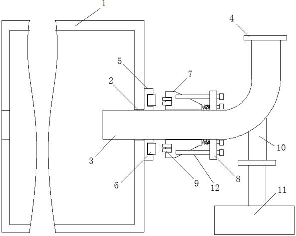
[0019] A sealing mechanism for the grinding head of a wet ball mill, in which a connection port 2 is provided on one side of the grinding head cylinder body, one end of the elbow 3 is inserted into the connection port 2, and the other end of the elbow 3 is connected to the mixer through a flange 4; Outside the connection port 2 between the cylinder body 1 and the elbow 3, a side motion base 5 of the cylinder body is arranged, and a groove around the elbow 3 is arranged on the side motion base 5 of the cylinder body. The dynamic sealing ring 6 is installed on the side motion of the cylinder body. In the groove of the base 5; the elbow side static base 7 and the static base pressing frame 8 that are set outside the feed end elbow 3, the elbow side static base 7 faces the side of the cylinder side moving base 5 A groove is set on the surface, and the static sealing ring 9 is installed in the groove of the static base 7 on the side of the elbow. The end face of the static seal rin...

Embodiment 2

[0021] As a specific preferred design, the side moving base 5 of the cylinder is made of metal material (such as: the side moving base 5 of the cylinder is made of 2205 stainless steel), the static base 7 of the elbow side is made of rubber, and the dynamic sealing ring 6 and The joint surface material of the static sealing ring 9 is silicon carbide.

[0022] As a preferred design, a positioning and fixing pipe 10 is installed on the elbow 3, and the other end of the positioning and fixing pipe 10 is provided with a positioning flange, and the positioning flange is connected with the base 11 installed on the ground.

[0023] As a specific structural design, the cylinder side moving base 5 has a thickness of 20mm, and a groove with a depth of 10mm and a width of 40mm is provided; the width*thickness of the dynamic sealing ring is 38mm*15mm.

[0024] As a preference, a 1mm rubber gasket is provided between the dynamic sealing ring 6 and the cylinder side dynamic base 5 to preven...


PUM


Abstract

The invention discloses a sealing mechanism of a grinding head of a wet ball mill. The sealing mechanism is characterized in that a connecting port is arranged at one side of a grinding head cylinder, one end of an elbow is inserted into the connecting port, and the other end of the elbow is connected to a mixer through a flange; a cylinder side moving base is arranged outside the connecting port of the grinding head cylinder and the elbow, a groove surrounding the elbow by a circle is arranged in the cylinder side moving base, and a rotating seal ring is arranged in the groove of the cylinder side moving base; and an elbow side static base and a static base pressing frame are arranged outside the elbow at the feeding end in a sleeving mode, a groove is arranged in the face, facing the cylinder side moving base, of the elbow side static base, a stationary seal ring is arranged in the groove of the elbow side static base, and the static base pressing frame presses the elbow side static base to the cylinder side moving base, so that the end face of the stationary seal ring makes contact with the end face of the rotating seal ring. The sealing mechanism completely solves the problems of slurry leakage and severe abrasion of the feeding elbow and the cylinder, the service life is at least two years, only the rotating seal ring and the stationary seal ring need to be replaced after abrasion, the connecting structure is simple, and replacement is extremely convenient.

Description

technical field [0001] The invention relates to a wet ball mill, in particular to a sealing mechanism for a grinding head of the wet ball mill. Background technique [0002] Wet ball mill is a low-speed ball mill with a speed of 15-25rpm, which is used in thermal power plants to prepare desulfurizer slurry. It uses a low-speed rotating drum to drive the steel balls in the drum to move, and through the impact, extrusion and grinding of the limestone blocks by the steel balls, the limestone blocks are broken and fine powder is ground. Its grinding part is a cylinder, which is lined with a wear-resistant rubber sleeve, and there is a layer of asbestos liner between the armor and the cylinder for sound insulation. The barrel of the ball mill is loaded with a certain number of diameter steel balls, the material to be ground and an appropriate amount of water, and the material, water and grinding body are properly matched according to the process requirements. The cylinder rotat...

Claims


Application Information

Patent Timeline
Patent Type & Authority Applications(China)
IPC IPC(8): B02C17/18F16J15/34
CPCB02C17/18F16J15/3452F16J15/3464F16J15/3496
Inventor 郭俊海郑伟娄海涛张兴李正阳刘永薇
Owner ANHUI HUADIAN SUZHOU POWER GENERATION
Learn More