Sludge drier and drying method

A sludge drying and sludge technology, which is applied in the field of solid waste resource treatment, can solve the problems of sludge wear and blockage on drying devices, and achieve the effect of reducing the amount of flue gas treatment and saving costs.

Pending Publication Date: 2016-06-15
SHENWU TECH GRP CO LTD
View PDF5 Cites 0 Cited by
  • Summary
  • Abstract
  • Description
  • Claims
  • Application Information

AI Technical Summary

Problems solved by technology

[0004] The purpose of the present invention is to provide a sludge drying machine and a drying method. During the drying process, no sealing device is required, and the sludge is kept in a static state relative to the material bed, thereby solving the problem of sludge causing the drying device The problem of serious wear and clogging, avoiding the generation of a large amount of dust, no risk of explosion, and realizing large-scale industrial treatment of sludge drying

Method used


Image

  • Sludge drier and drying method
  • Sludge drier and drying method
  • Sludge drier and drying method

Examples


Embodiment 1

[0036] Embodiment 1 A kind of sludge drying machine

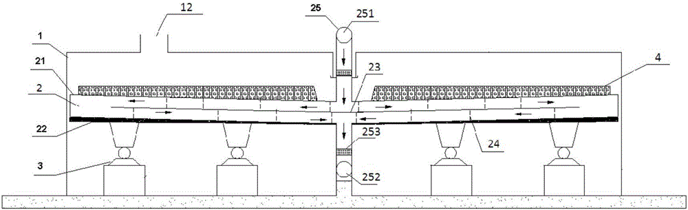
[0037] A sludge dryer, such as figure 1 , figure 2 As shown, it includes a cylindrical cavity 1, a material bed 2 arranged horizontally in the cavity, and a driving device 3 for driving the material bed to rotate horizontally;

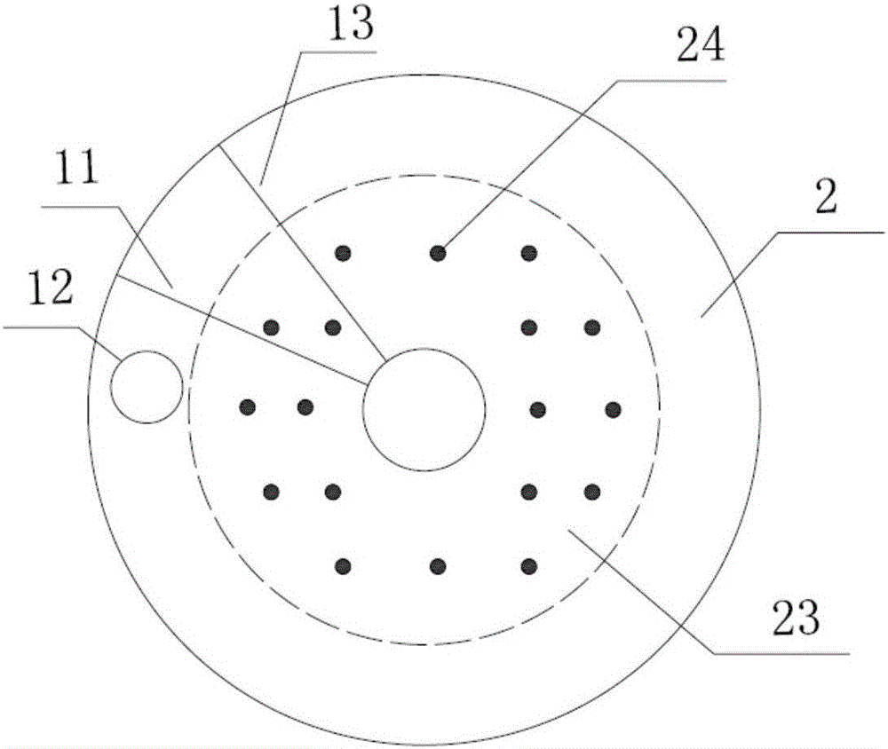
[0038] The material bed 2 is a rotating hollow cylinder structure, and a circular baffle 23 coaxial with the material bed is horizontally arranged between the upper and lower bottom plates 21, 22 of the material bed, and the inner space of the material bed is divided into upper and lower parts. Two layers; the diameter of the circular baffle is smaller than the diameter of the material bed;

[0039] A heat medium pipeline 25 perpendicular to the material bed and communicating with the material bed is also arranged at the center of the material bed;

[0040] The surface of the cavity is provided with a sludge feed port 11, a drying flue gas outlet 12, and a sludge discharge port 13; wherein, the ...

Embodiment 2

[0044] Embodiment 2 A kind of sludge drying machine

[0045] A sludge dryer, similar in structure to Embodiment 1, the only difference is that the diameter of the baffle plate 23 is 75% of the diameter of the material bed 2 .

Embodiment 3

[0046] Embodiment 3 A kind of sludge drying method

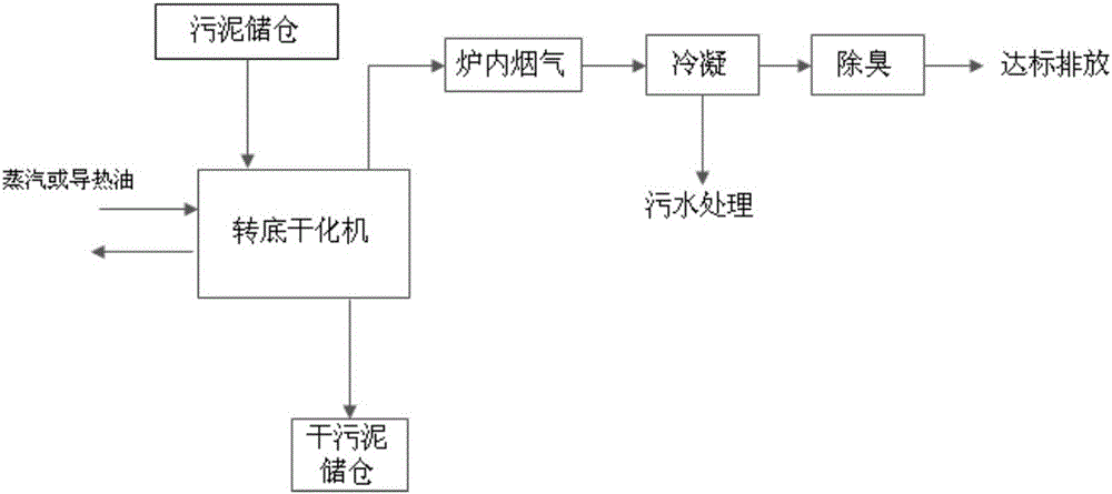
[0047] A method for drying sludge using the sludge dryer described in Example 1, as shown in 3, includes the following steps:

[0048] (1) Send the sludge (moisture content 80%) from the sewage treatment plant into the sludge storage bin, transport it to the sludge dryer through the sludge pump, and feed it from the feeding device located on one side of the dryer;

[0049]The sludge is evenly arranged on the surface of the upper bottom plate of the material bed of the sludge dryer through the material distribution mechanism, and the thickness of the sludge is 10mm; the material bed is in contact with the outer wall of the cavity, and does not need to be sealed, and the atmosphere in the dryer is generated by drying. Flue gas and part of the air containing water vapor;

[0050] (2) The heat medium enters the material bed through the heat medium pipeline, and circulates between the upper and lower layers of the material bed a...


PUM

PropertyMeasurementUnit
thicknessaaaaaaaaaa

Abstract

The invention relates to a sludge drying machine and a drying method. The sludge drying machine includes a cavity, a horizontally arranged material bed located in the cavity, and a driving device for driving the horizontal rotation of the material bed; the material bed is a rotating hollow cylinder structure, and the upper and lower bottom plates of the material bed A circular baffle plate coaxial with the material bed is arranged horizontally between them, and the internal space of the material bed is divided into upper and lower layers; the diameter of the circular baffle plate is smaller than the diameter of the material bed; a The heat medium pipeline is perpendicular to the material bed; the surface of the cavity is provided with a sludge inlet, a drying flue gas outlet, and a sludge outlet; wherein the flue gas outlet is close to the sludge inlet. The invention solves the problem of severe wear and tear on the device by the sludge with large sand content; and does not generate a large amount of dust in the drying process, does not have the danger of explosion, does not need to control the oxygen content in the furnace; and does not have the problem of blockage and jamming.

Description

technical field [0001] The invention relates to a sludge drying machine and a drying method, belonging to the technical field of solid waste resource treatment. Background technique [0002] Sludge is a kind of solid organic waste with extremely high water content. Even the sludge that has been pretreated by concentration and centrifugation has a water content of about 80%. Sludge treatment generally includes front-end drying treatment and terminal disposal. Terminal disposal technologies such as sludge landfill require a moisture content of less than 60%, and sludge incineration requires a moisture content of about 40%. Therefore, no matter what kind of terminal disposal technology is adopted, the key point of the technology lies in how the front-end can remove the moisture in the sludge simply, efficiently and energy-saving so that the raw materials can meet the final disposal requirements. [0003] At present, thermal drying technology is mainly used for sludge drying, b...

Claims


Application Information

Patent Timeline
Patent Type & Authority Applications(China)
IPC IPC(8): C02F11/12
CPCC02F11/12C02F2303/06
Inventor 贾懿曼张安强任浩华蔡先明陶进峰吴道洪
Owner SHENWU TECH GRP CO LTD
Why Eureka
Try Eureka