Sludge drying machine and drying method

A sludge drying and sludge technology, applied in the field of solid waste recycling, can solve problems such as device wear and blockage, and achieve the effects of solving severe wear, ensuring moisture content, and increasing drying capacity.

Pending Publication Date: 2016-05-04
SHENWU TECH GRP CO LTD
View PDF5 Cites 0 Cited by
  • Summary
  • Abstract
  • Description
  • Claims
  • Application Information

AI Technical Summary

Problems solved by technology

[0004] The object of the present invention is to provide a sludge drying machine and a drying method. Through indirect heating, the sludge remains still relative to the distribution plate during the drying process, which solves the problem of serious wear and blockage of the sludge on the device, and the device does not need Hermetically sealed, avoiding the danger of explosion, easy to achieve large-scale handling

Method used


Image

  • Sludge drying machine and drying method
  • Sludge drying machine and drying method
  • Sludge drying machine and drying method

Examples


Embodiment 1

[0037] Embodiment 1 A kind of sludge drying machine

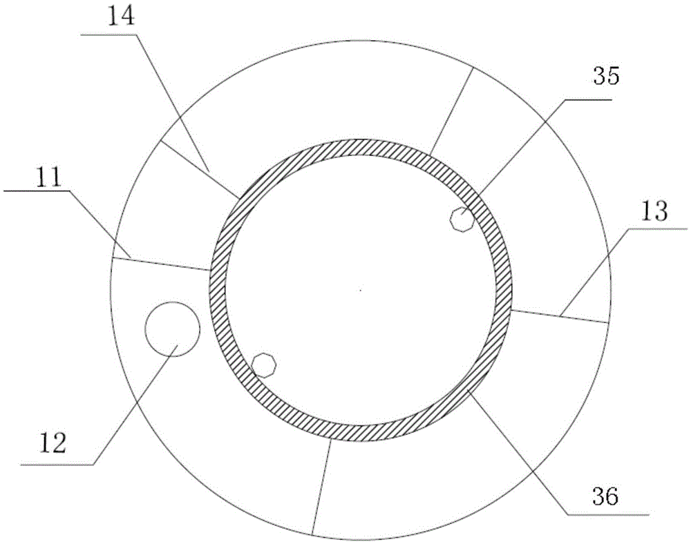
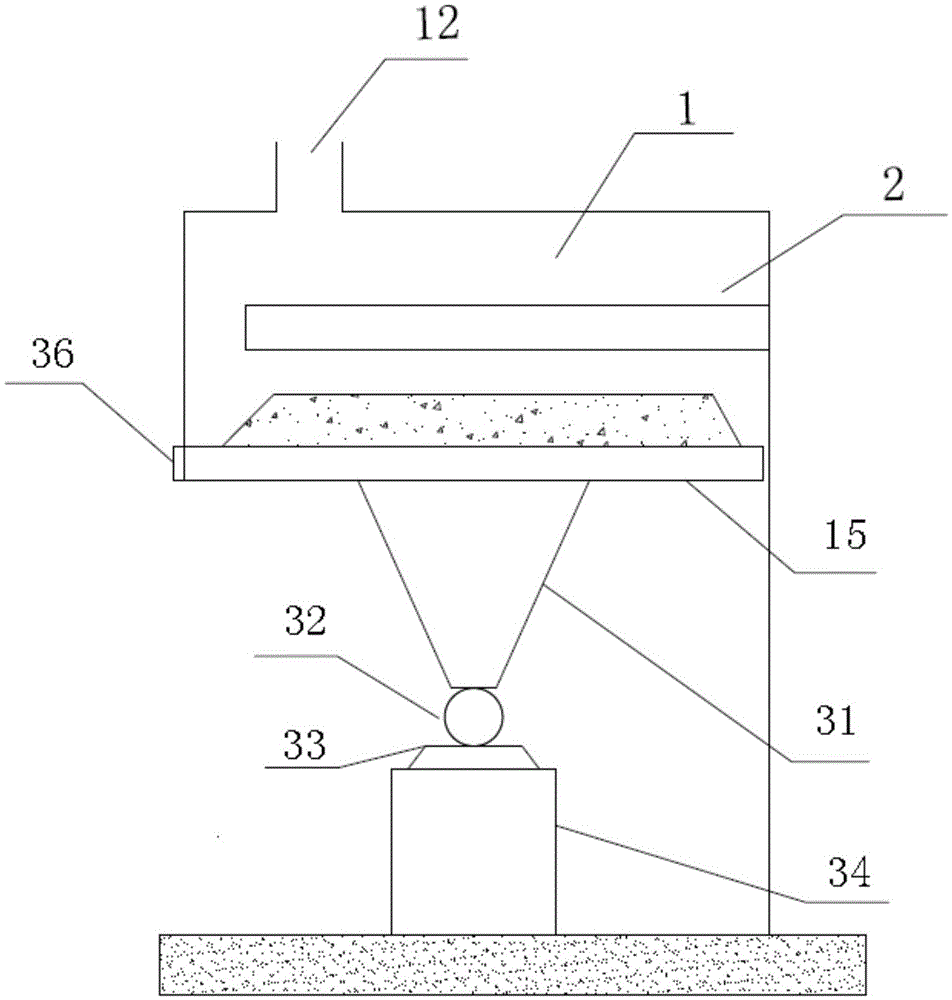
[0038] A sludge dryer, such as figure 2 , image 3 As shown, it includes: an annular hollow cavity 1, the bottom surface of the cavity is used as a distribution pan 15, and it is set to rotate horizontally relative to the side wall and top of the cavity, and on the side wall of the cavity A sludge outlet (including an intermediate sludge outlet 13 and a final sludge outlet 14) is provided, and the cavity is also provided with a drying flue gas outlet 12 and a sludge inlet 11. Wherein, the dried flue gas outlet is arranged on the top of the cavity and is located near the sludge feed port;

[0039] A driving device 3, the driving device is arranged under the distribution pan 15, and is used to drive the distribution pan to rotate;

[0040] The radiation heating device 2 is arranged inside the cavity 1, fixed on the side wall of the cavity and arranged parallel to the distribution pan.

[0041] Wherein, the distributing p...

Embodiment 2

[0048] Embodiment 2 A kind of sludge drying method

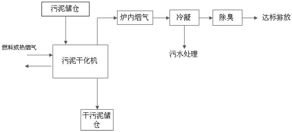
[0049] A kind of drying method that utilizes the sludge drying machine described in embodiment 1 to process sludge, such as figure 1 shown, including the following steps:

[0050] (1) Send the sludge (moisture content 80%) from the sewage treatment plant into the sludge storage bin, transport it to the sludge dryer through the sludge pump, and feed it from the feeding device located on one side of the dryer;

[0051] The sludge is evenly arranged on the distribution plate of the drying machine through the material distribution mechanism. The total thickness of the sludge is 60mm; the distance between the radiation heating device and the highest point of the sludge is 15mm; the entire cavity does not need to be sealed;

[0052] (2) The sludge on the distributing pan is heated and dried by radiation through the radiation heating device. During the drying process, the sludge moves through the rotation of the distributing pan; ...

Embodiment 3

[0056] Embodiment 3 A kind of sludge drying method

[0057] A method for drying sludge by using the sludge dryer described in Example 1, comprising the steps of:

[0058] (1) Sludge (moisture content 85%) from the sewage treatment plant is sent to the sludge storage bin, transported to the sludge dryer by the sludge pump, and fed by the feeding device located on one side of the dryer.

[0059] The sludge is evenly arranged on the distribution plate of the drying machine through the material distribution mechanism. The total thickness of the sludge is 20mm; the distance between the radiation heating device and the highest point of the sludge is 25mm; the entire cavity does not need to be sealed;

[0060] (2) The sludge on the distributing pan is heated and dried by radiation through the radiation heating device. During the drying process, the sludge moves through the rotation of the distributing pan;

[0061] Wherein, the drying temperature is 180°C, the total sludge drying ti...


PUM

PropertyMeasurementUnit
thicknessaaaaaaaaaa
thicknessaaaaaaaaaa
thicknessaaaaaaaaaa

Abstract

The invention relates to a sludge drying machine and drying method. The sludge drying machine comprises an annular hollow cavity, a driving device and a radiation heating device, wherein the bottom surface of the cavity serves as a distribution tray and is arranged to horizontally rotate relative to the side wall and top of the cavity; a sludge discharge hole is formed in the side wall of the cavity; the cavity is also provided with a dried smoke outlet and a sludge feeding hole; the dried smoke outlet is formed in the top of the cavity and is near the sludge feeding hole; the driving device is arranged below the distribution tray and is used for driving the distribution tray to rotate; the radiation heating device is arranged inside the cavity, is fixed on the side wall of the cavity and is arranged to be parallel to the distribution tray. By adopting the sludge drying machine and drying method, the problem that devices are seriously worn by sludge with high sand content is solved; plenty of dust is not generated, explosion dangers do not exist and the oxygen content of furnaces is unnecessary to be controlled in the drying process; the problem of blocking does not exist.

Description

technical field [0001] The invention relates to a sludge drying machine and a drying method, belonging to the technical field of solid waste resource treatment. Background technique [0002] Sludge is a kind of solid organic waste with extremely high water content. Even the sludge that has been pretreated by concentration and centrifugation has a water content of about 80%. Sludge treatment generally includes front-end drying treatment and terminal disposal. Terminal disposal technologies such as sludge landfill require a moisture content of less than 60%, and sludge incineration requires a moisture content of about 40%. Therefore, no matter what kind of terminal disposal technology is adopted, the key point of the technology lies in how the front-end can remove the moisture in the sludge simply, efficiently and energy-saving so that the raw materials can meet the final disposal requirements. [0003] At present, thermal drying technology is mainly used for sludge drying, b...

Claims


Application Information

Patent Timeline
Patent Type & Authority Applications(China)
IPC IPC(8): C02F11/12
CPCC02F11/12C02F2303/06
Inventor 贾懿曼巴玉鑫陶进峰吴小飞王惠惠吴道洪
Owner SHENWU TECH GRP CO LTD
Why Eureka
Try Eureka