A vibrating screen vibration system

A resonant sieve and vibration excitation technology, applied in the direction of sieve, solid separation, grille, etc., can solve the problems affecting the normal operation of the sieve machine, the wear of the resonance spring, the spring falling off, etc., to solve the problem of serious wear, reduce the failure rate, Guaranteed normal operation

Active Publication Date: 2016-02-03
TANGSHAN LANDSKY TECH
View PDF6 Cites 0 Cited by
  • Summary
  • Abstract
  • Description
  • Claims
  • Application Information

AI Technical Summary

Problems solved by technology

[0002] In recent years, a new type of resonant vibrating screen has appeared. In this vibrating screen, the surroundings of the working net are connected with the screen frame, and the resonance frame is set under the working net and parallel to the working net. The resonance spring connection on the inside of the frame uses the vibrating motor unit to drive the screen box for linear vibration, and at the same time uses the inertia resonance of the resonance frame to strike the working net to make the working net produce compound vibrations. And the structure is simple, and it is favored by the fine-grained material screening industry. However, due to the combination of resonance frames that generate compound vibrations on the working net through knocking—the design defect of the compound excitation system: the resonance used to transmit the excitation force The axial direction of the spring is not consistent with the vibration direction of the screen box, resulting in serious wear and tear of the resonance spring, and frequent occurrence of spring shedding, which seriously affects the normal operation of the screen machine. Improve the structure of the vibration system

Method used


Image

  • A vibrating screen vibration system
  • A vibrating screen vibration system

Examples


Embodiment Construction

[0011] The present invention will be further described below in conjunction with the accompanying drawings and embodiments, but the protection scope of the present invention is not limited.

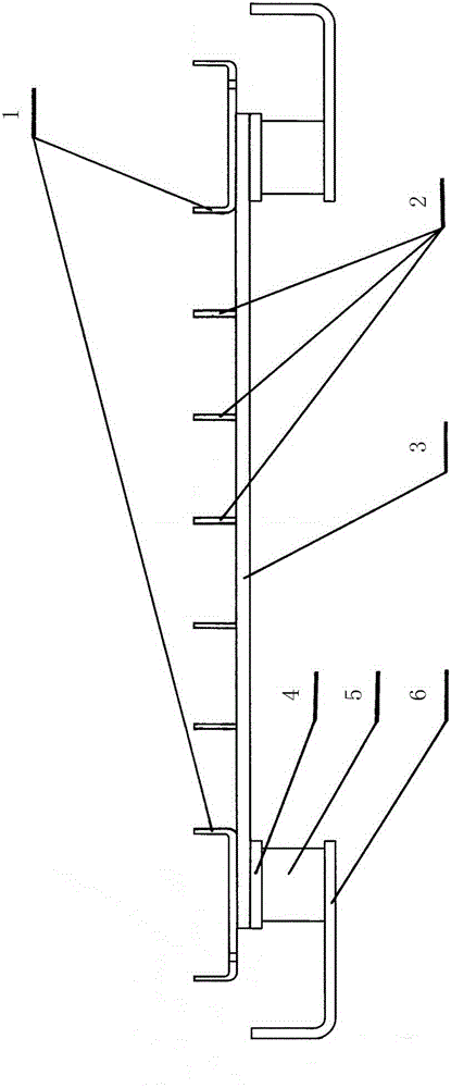
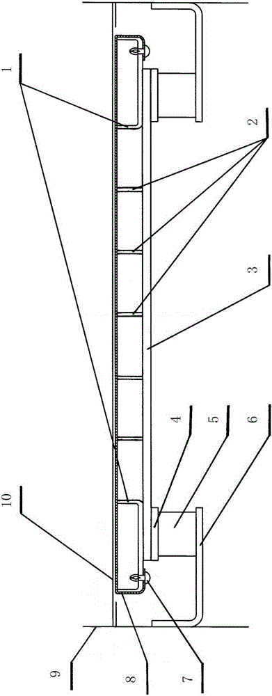
[0012] Referring to the accompanying drawings, the embodiment of the present invention provides an improved compound excitation system for a resonant vibrating screen, that is, a vibrating screen excitation system, which consists of an exciting row, an exciting row connecting frame 3 and an A resonant spring 5 is arranged at each of the four corners below the connecting frame 3. The resonant spring 5 is a columnar spring and is installed upright. 3 connection, the lower end is fixed on the lower spring support seat 6 fixed on the inner side of the screen frame 9; the excitation row includes the fixed support net excitation row 1 installed on the two ends of the excitation row connection frame 3 respectively and the two fixed The support net excitation row 2 between the support net excitat...


PUM


Abstract

The invention relates to a complex excitation system for a resonant type vibrating screen and discloses a resonance screen excitation system. The resonance screen excitation system consists of excitation ranks, an excitation connection frame and four resonance springs arranged at four corners of the lower portion of the excitation connection frame; by means of the resonance screen excitation system, the problem that existing complex excitation systems for resonant type vibrating screens are poor in reliability is solved; the structure is simple, and a spring transmission excitation force which is parallel to a screen machine vibration direction is used, so that the problem of serious abrasion of the resonant type spring is solved, the fault rate of the complex excitation system is greatly reduced, and normal operation of the resonant screen is guaranteed; if the resonant screen is used as a device for arranging and tensioning a support net, hook plates and fixing bolts used for connecting a screen frame and the resonant screen to arrange and tension the support net are reduced, vibration mass of the screen box combination is reduced, workload of the spring bearing the screen box combination is reduced, service life of the spring is prolonged, meanwhile, fault hidden danger brought by fixed bolt looseness caused by vibration during usage is fundamentally eliminated, and the fault rate of the vibration screen is further reduced.

Description

technical field [0001] The invention relates to a vibrating screen excitation system, in particular to an improved compound excitation system for a resonant vibrating screen, which belongs to the technical field of separation equipment. Background technique [0002] In recent years, a new type of resonant vibrating screen has emerged. In this vibrating screen, the surroundings of the working net are connected with the screen frame, and the resonance frame is set under the working net and parallel to the working net. The resonance spring connection on the inside of the frame uses the vibrating motor unit to drive the screen box for linear vibration, and at the same time uses the inertia resonance of the resonance frame to strike the working net to make the working net produce compound vibrations. And the structure is simple, and is favored by the fine-grained material screening industry. However, due to the combination of resonance frames that generate compound vibrations on ...

Claims


Application Information

Patent Timeline
Patent Type & Authority Patents(China)
IPC IPC(8): B07B1/42
Inventor 李松奕刘维生
Owner TANGSHAN LANDSKY TECH
Why Eureka
Try Eureka