

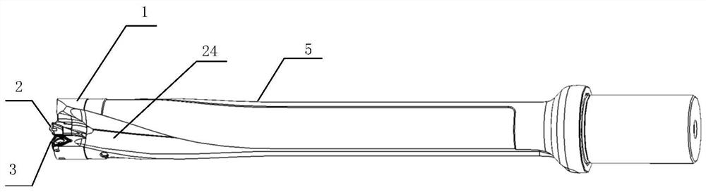
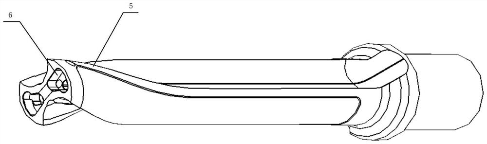
Split type drilling tool
A split-type drilling tool technology, which is applied in drilling tool accessories, drill repairing, manufacturing tools, etc., can solve the problems of affecting service life and drilling accuracy, high cost of drill body loss, and scrapping of the whole rod, etc., to achieve structural coordination Stability and use stability guarantee, guaranteed service life, long service life effect
- Summary
- Abstract
- Description
- Claims
- Application Information
AI Technical Summary
Problems solved by technology
Method used
Image

Examples
Embodiment Construction
[0049] The present invention will be further described in detail below in conjunction with the accompanying drawings, so that those skilled in the art can implement it with reference to the description.
[0050] It should be understood that terms such as "having", "comprising" and "including" as used herein do not entail the presence or addition of one or more other elements or combinations thereof.
[0051] It should be noted that in the description of the present invention, the orientation or positional relationship indicated by the term is based on the orientation or positional relationship shown in the drawings, which is only for the convenience of describing the present invention and simplifying the description, and does not indicate or imply No device or element must have a specific orientation, be constructed, and operate in a specific orientation and therefore should not be construed as limiting the invention. In addition, the terms "first" and "second" are used for de...
PUM
 Abstract
Description
Claims
Application Information