
Manipulator for industrial workshop automatic production line

An automated production line and manipulator technology, applied in the direction of manipulators, program-controlled manipulators, manufacturing tools, etc., can solve the problems of falling objects, poor manipulator adaptability, low stability, etc.

Inactive Publication Date: 2021-04-27
NANJING NIEBO INTERNET OF THINGS TECH CO LTD
View PDF0 Cites 2 Cited by
  • Summary
  • Abstract
  • Description
  • Claims
  • Application Information

AI Technical Summary

Problems solved by technology

[0004] The purpose of the present invention is to solve the problem that the grasping size of the grasping mechanism of the existing production line manipulator is a fixed value, which cannot be changed flexibly, resulting in poor adaptability and low practicability of the manipulator. At the same time, the existing production line manipulator When moving items, there is no device to further clamp them, and the items to be moved may be in danger of falling, and the stability is low, which cannot meet the actual work needs. An automated production line for industrial workshops is proposed with manipulator

Method used


Image

  • Manipulator for industrial workshop automatic production line
  • Manipulator for industrial workshop automatic production line
  • Manipulator for industrial workshop automatic production line

Examples


Embodiment 1

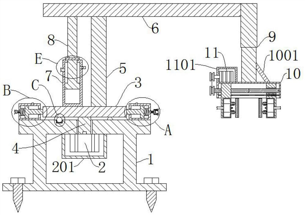
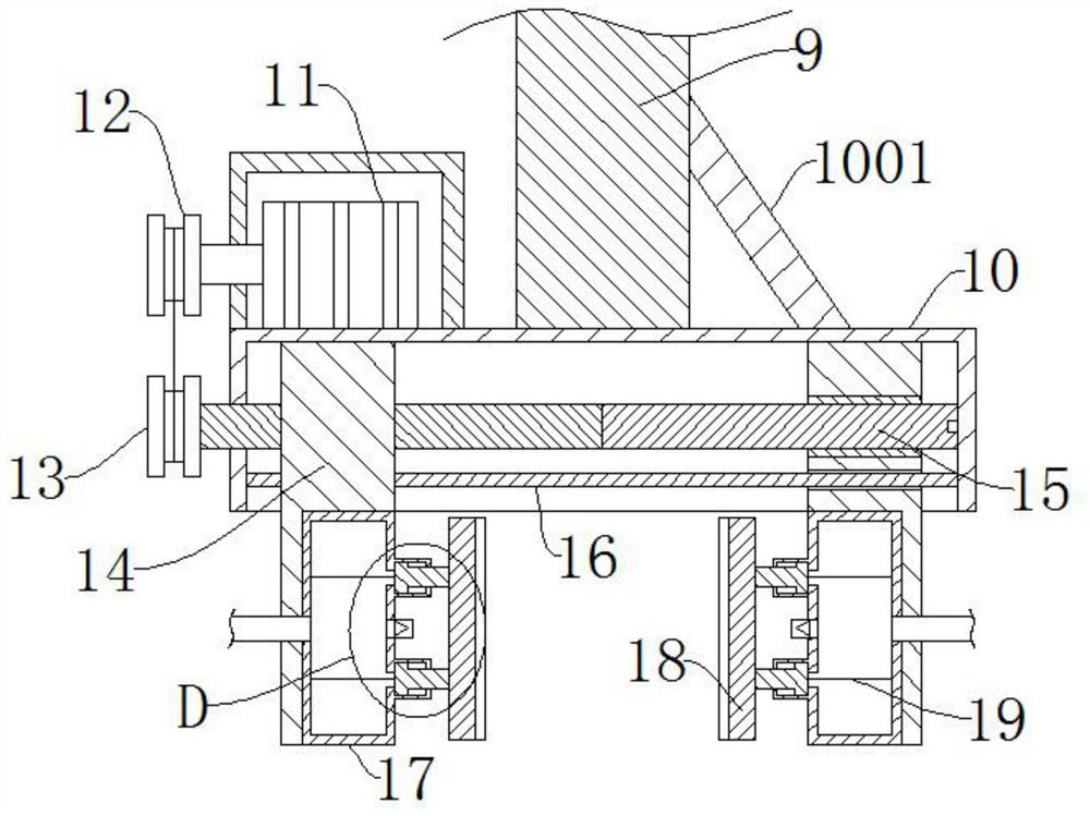
[0031] refer to Figure 1-8 , a manipulator for an automated production line in an industrial workshop, comprising a base 1 and a first motor 2, the base 1 and the first motor 2 are fixedly connected, the output end of the first motor 2 is fixedly connected to a rotating shaft 4, and the rotating shaft 4 is far away from the first motor. One end of a motor 2 runs through the base 1, and is fixedly connected with a rotating plate 3, and the rotating plate 3 is fixedly connected with a column 5, and the upper end of the column 5 is fixedly connected with a fixed rod 6, and the end of the fixed rod 6 away from the column 5 is fixedly connected with a telescopic The lower end of the rod 9 telescopic rod 9 is fixedly connected with a fixed box 10, and two symmetrical bearing blocks 14 are slidably connected in the fixed box 10, and the forward and reverse screw mandrel 15 is connected with the rotation in the fixed box 10, and the forward and reverse screw mandrel 15 is connected wi...

Embodiment 2

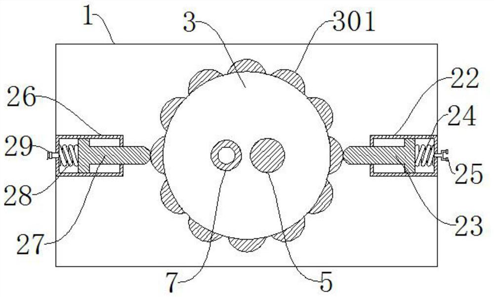
[0034] refer to Figure 1-8 , a manipulator for an automated production line in an industrial workshop, which is basically the same as in Embodiment 1, and furthermore: one side of the upper end of the rotating plate 3 is fixedly connected to the cylinder 7, and one side of the upper end of the cylinder 7 is provided with an air inlet, and the cylinder 7 is away from One end of the air inlet is provided with a safety valve, the cylinder 7 is sealed and slidably connected with a moving column 8, the upper end of the moving column 8 is fixedly connected with the fixed rod 6, and the opening of the cylinder 7 and the moving column 8 are sealed by a seal 701 , the upper end of the base 1 away from the second cylinder 22 is fixedly connected with the third cylinder 26, the third cylinder 26 is slidingly connected with the second piston 27, the second piston 27 is attached to the arc-shaped protrusion 301, the third cylinder 26 is fixedly connected with an air outlet pipe 29 at one ...

Embodiment 3

[0036] refer to Figure 1-8 , a manipulator for an automated production line in an industrial workshop, which is basically the same as in Embodiment 1, furthermore: grooves are provided on both sides of the upper end of the base 1, and balls 101 are rollingly connected in the grooves, and the balls 101 are connected to the bottom of the rotating plate 3 Stick to each other, improve the stability of the rotating plate 3, and prevent the rotating plate 3 from tilting due to the overweight of the object to be moved, which will affect the work progress.


PUM


Abstract

The invention discloses a manipulator for an industrial workshop automatic production line, and belongs to the technical field of mechanical design. The manipulator for the industrial workshop automatic production line comprises a base and a first motor, the base is fixedly connected with the first motor, the output end of the first motor is fixedly connected with a rotating shaft, the end, away from the first motor, of the rotating shaft penetrates through the base and is fixedly connected with a rotating plate, a stand column is fixedly connected to the rotating plate, and the upper end of the stand column is fixedly connected with a fixing rod. By arranging a second motor, a positive and negative rotation lead screw and clamping plates, the manipulator can grab objects of different specifications, the flexibility is high, and the practicability of the manipulator is effectively improved; and by arranging first air cylinders, a second air cylinder and arc-shaped protruding blocks, the clamping plates can further clamp the objects, and the danger that the objects needing to be moved fall off in the moving process is avoided, so that the stability of the manipulator is effectively improved, and the actual use requirement is met.

Description

technical field [0001] The invention relates to the technical field of mechanical design, in particular to a manipulator for an automatic production line in an industrial workshop. Background technique [0002] A manipulator is an automatic operating device that can imitate certain movement functions of the human hand and arm to grab, carry objects or operate tools according to a fixed program. It is characterized in that it can be programmed to complete various expected operations. Combining the advantages of both human beings and manipulators, the manipulator is the earliest industrial robot and the earliest modern robot. It can replace the heavy labor of people to realize the mechanization and automation of production. Industrial manipulators are an important part of the automated production line. , has become the core of the modern manufacturing production system, especially in the harsh working environment, the use of feeding devices to achieve mechanization and automat...

Claims


Application Information

Patent Timeline
Patent Type & Authority Applications(China)
IPC IPC(8): B25J9/00B25J9/10B25J15/02B25J19/00B65G47/90
CPCB25J9/0009B25J9/10B25J15/0253B65G47/90
Inventor 王宇益袁荣小
Owner NANJING NIEBO INTERNET OF THINGS TECH CO LTD
Learn More