Regional constant negative pressure vacuum system

A vacuum system and sub-regional technology, applied in the field of cutting beds, can solve the problems of time-consuming and laborious, unable to achieve the effect of adsorption, and the fabric cannot be adsorbed with high suction force.

Pending Publication Date: 2021-04-27
WUHAN KEPUYINENG TECH CO LTD
View PDF0 Cites 0 Cited by
  • Summary
  • Abstract
  • Description
  • Claims
  • Application Information

AI Technical Summary

Problems solved by technology

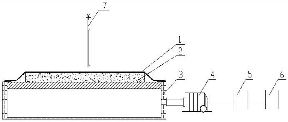
[0003] However, with more and more types of fabrics, there are some fabrics that cannot absorb with high suction, such as sponge, pearl cotton, SCR, SBR (a kind of fabric used to make diving suits), if the suction is too large, it will deform, such as Figure 2a to Figure 2d shown
Therefore, fabrics that cannot be used with a full-load vacuum need a small suction to absorb, and under a small suction, when the blade starts cutting, there will be air leakage, and the suction will drop at this time, and the adsorption effect will not be achieved.
In order to achieve the adsorption effect, it is necessary to stop the machine to increase the suction, which is time-consuming and labor-intensive.

Method used


Image

  • Regional constant negative pressure vacuum system
  • Regional constant negative pressure vacuum system
  • Regional constant negative pressure vacuum system

Examples


Embodiment Construction

[0020] Embodiments of the present invention are described below through specific examples, and those skilled in the art can easily understand other advantages and effects of the present invention from the content disclosed in this specification. The present invention can also be implemented or applied through other different specific implementation modes, and various modifications or changes can be made to the details in this specification based on different viewpoints and applications without departing from the spirit of the present invention. It should be noted that, in the case of no conflict, the following embodiments and features in the embodiments can be combined with each other.

[0021] It should be noted that the diagrams provided in the following embodiments are only schematically illustrating the basic ideas of the present invention, and only the components related to the present invention are shown in the diagrams rather than the number, shape and shape of component...


PUM


Abstract

The invention discloses a regional constant negative pressure vacuum system. The system comprises a sealed cavity with a breathable supporting platform on the top surface; a negative pressure vacuum adsorption cavity is formed by the sealed cavity and a covering film arranged on the sealed cavity; a plurality of cavity partition plates are arranged in the sealed cavity and divide the negative pressure vacuum adsorption cavity into a plurality of sub-negative pressure vacuum adsorption cavities; the upper portion of each sub-negative pressure vacuum adsorption cavity directly faces the covering film; each sub-negative pressure vacuum adsorption cavity communicates with an exhaust pipe of a vacuum negative pressure pump; a driving motor of the vacuum negative pressure pump is connected with a variable frequency controller; the variable frequency controller is connected with a controller; a negative pressure sensor is further arranged in each sub-negative pressure vacuum adsorption cavity; and each negative pressure sensor is electrically connected with the controller. According to the invention, vacuum negative pressure values in the plurality of sub-negative pressure vacuum adsorption cavities can be automatically adjusted, so that the system is more energy-saving and environment-friendly; and manual intervention is not needed in the whole process, so that the manual frequency modulation procedure of personnel is reduced, and the fabric cutting effect is guaranteed.

Description

technical field [0001] The invention relates to the field of cutting bed technology, in particular to a sub-area constant negative pressure vacuum system. Background technique [0002] Vacuum negative pressure is one of the necessary functions of the CNC cutting machine in the garment cutting industry. The fabric forms a sealed cavity between the covering film and the machine tool cavity, and the air in the cavity is extracted by a negative pressure pump. Under the action of atmospheric pressure, negative The greater the air flow rate per unit time and the greater the negative pressure value of the air drawn by the pressure pump, the more firmly the fabric is fixed. At present, most cutting machines on the market control the vacuum chamber through preset frequency control or fixed frequency control, and some directly turn on the vacuum pump to run at the rated speed. Vacuum systems for conventional cutting machines, such as figure 1 As shown, the controller 6 sends an orde...

Claims


Application Information

Patent Timeline
IPC IPC(8): D06H7/00B26D7/01
CPCB26D7/018D06H7/00
Inventor 张晓东
Owner WUHAN KEPUYINENG TECH CO LTD
Why Eureka
Try Eureka