
Spiral ball speed reducer

A technology of ball reducer and helix, which is applied in transmission devices, components with teeth, friction transmission devices, etc. It can solve the problems of unavoidable backlash, large size of reducer, and accuracy error, etc., and achieve reduced friction and small size , the effect of reducing production costs

Active Publication Date: 2021-04-27
JILIN UNIV
View PDF9 Cites 0 Cited by
  • Summary
  • Abstract
  • Description
  • Claims
  • Application Information

AI Technical Summary

Problems solved by technology

However, these commonly used reducer transmission methods are all through gear meshing transmission. In the process of gear transmission, backlash is inevitable, resulting in accuracy errors; frictional heat generation between gears and tooth root fractures and other failure forms also affect the deceleration. An important factor in the life of the gear reducer; industrial gear reducers are large in size and weight, so it is difficult to apply in many small volumes and small spaces, and urgently needs to be improved

Method used


Image

  • Spiral ball speed reducer
  • Spiral ball speed reducer
  • Spiral ball speed reducer

Examples


Embodiment Construction

[0021] The detailed content of the present invention and its specific implementation will be further described below in conjunction with the accompanying drawings.

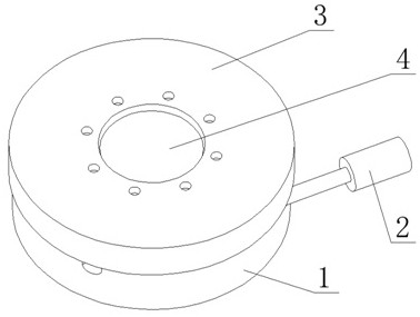
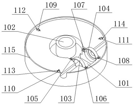
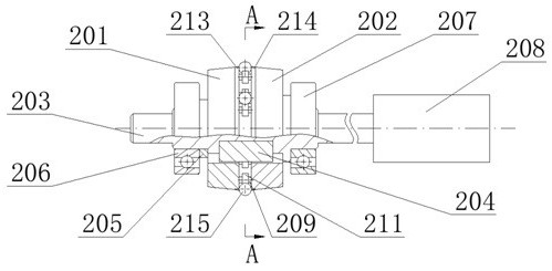
[0022] see Figure 1 to Figure 7 As shown, the helical ball reducer of the present invention includes a base 1, an input shaft assembly 2, an output shaft assembly 3, and a limit connection assembly 4. The base 1 is fixed on the ground or other fixtures, and the input shaft The assembly 2 is installed on the input shaft groove 101 of the base 1, and the output shaft assembly 3 is installed on the output shaft core 102 of the base 1. The outer surface of the power output volute 301 of the output shaft assembly 3 is smooth, and can be carried out as required. Drilling, suitable for various installation methods; the input shaft assembly 2 and the output shaft assembly 3 rely on the outer edge 115 of the base and the outer edge 303 of the output shaft assembly for radial positioning respectively, and rely on deep groo...


PUM


Abstract

The invention relates to a spiral ball speed reducer and belongs to the field of speed reducers. A base is fixed to the ground or a fixing part, an input shaft assembly is arranged on an input shaft groove of the base, and an output shaft assembly is arranged on an output shaft core of the base; the input shaft assembly and the output shaft assembly are limited in the radial direction through the outer edge of the base and the outer edge of the output shaft assembly respectively, friction is reduced through contact of deep groove ball bearings and the inner side face of the outer edge of the output shaft assembly, and balls in the input shaft assembly is meshed with a spiral slideway in the output shaft assembly to achieve a universal pure rolling transmission mode; and the base and the output shaft assembly are connected through a limiting connecting assembly for axial limiting, an movable limiting rings can rotate relative to supports. The spiral ball speed reducer has the advantages that meshing transmission of the balls and the spiral slideway is adopted, friction between the balls and the spiral slideway is greatly reduced through the universal pure rolling transmission mode of the balls, friction is further reduced through the movable limiting rings capable of rotating relative to the supports, abrasion and heat production are reduced, and the service life is prolonged; and no return difference exists and the precision is high.

Description

technical field [0001] The invention relates to the field of reducers, in particular to a helical ball reducer based on a helical slideway and balls. It is suitable for industrial robot joints, balance cars and other fields. Background technique [0002] Reducers are widely used in the machinery industry, mainly gears and worm gears. Small size, small weight and high precision are the goals pursued by the industry. However, these commonly used reducer transmission methods are all through gear meshing transmission. In the process of gear transmission, backlash is inevitable, resulting in accuracy errors; frictional heat generation between gears and tooth root fractures and other failure forms also affect the deceleration. An important factor in the life of the gear reducer; the industrial gear reducer is large in size and weight, so it is difficult to apply in many small volumes and small spaces, and needs to be improved urgently. Contents of the invention [0003] The o...

Claims


Application Information

Patent Timeline
Patent Type & Authority Applications(China)
IPC IPC(8): F16H13/08F16H57/023F16H57/021F16H57/02
CPCF16H13/08F16H57/023F16H57/021F16H57/02
Inventor 朱先勇肖雄魏子童罗彦茹唐荣耀孙炜佳王鹏樊跃香彭惠明宋鹏
Owner JILIN UNIV
Learn More