Inter-board microwave optical wireless transmission system

A wireless transmission, microwave light technology, applied in electromagnetic wave transmission system, transmission system, free space transmission and other directions, can solve the problems of difficult hardware, complex system interconnection, complex structure and so on

Pending Publication Date: 2021-04-27
CHINA AVIATION OPTICAL-ELECTRICAL TECH CO LTD
View PDF4 Cites 4 Cited by
  • Summary
  • Abstract
  • Description
  • Claims
  • Application Information

AI Technical Summary

Problems solved by technology

[0003] With the rapid development and in-depth application of microwave photonics technology, military equipment systems have more and more urgent demands on microwave optical transmission technology for "thinness, high integration, and multi-channel". The existing microwave optical fiber transmission system can no longer meet the requirements. The main problems are as follows: (1) The interconnection of the system is complex: In the existing microwave optical transmission system, the electrical signals are interconnected by coaxial cables when transmitting multi-channel microwave signals, and the optical signals are transmitted by optical fibers, which makes the interconnection of the entire system complicated; (2) Dimensions Large, low integration: The bending radius of the coaxial line and the optical fiber in the traditional microwave optical transmission system is large, and it is difficult to improve the integration during multi-channel transmission, resulting in an excessively large system size; (3) Poor reliability: With the microwave signal path Due to the increase in the number and the improvement of integration, the existing microwave optical transmission system has complex structure, difficult hardware, and difficult interconnection, which greatly reduces the reliability of the system.

Method used


Image

  • Inter-board microwave optical wireless transmission system
  • Inter-board microwave optical wireless transmission system
  • Inter-board microwave optical wireless transmission system

Examples


Embodiment Construction

[0027] Further detailed description will be made below in conjunction with the accompanying drawings and preferred embodiments.

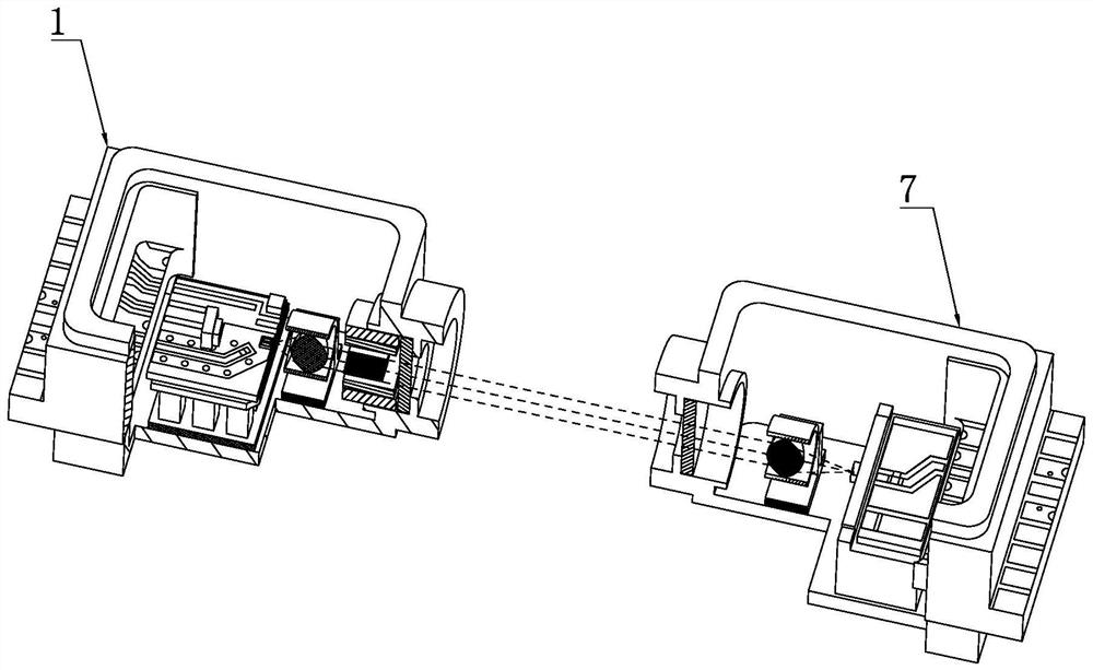
[0028] A specific example of an inter-board microwave-optical wireless transmission system Figure 1 to Figure 3 , which includes optical transmitting components and optical receiving components, which can realize the modulation of microwave optical signals, optical wireless transmission and demodulation of microwave optical modulation signals, so as to complete the modulation and demodulation of 18GHz bandwidth microwave signals and the distance between optical modulation signals of 50mm transmission.

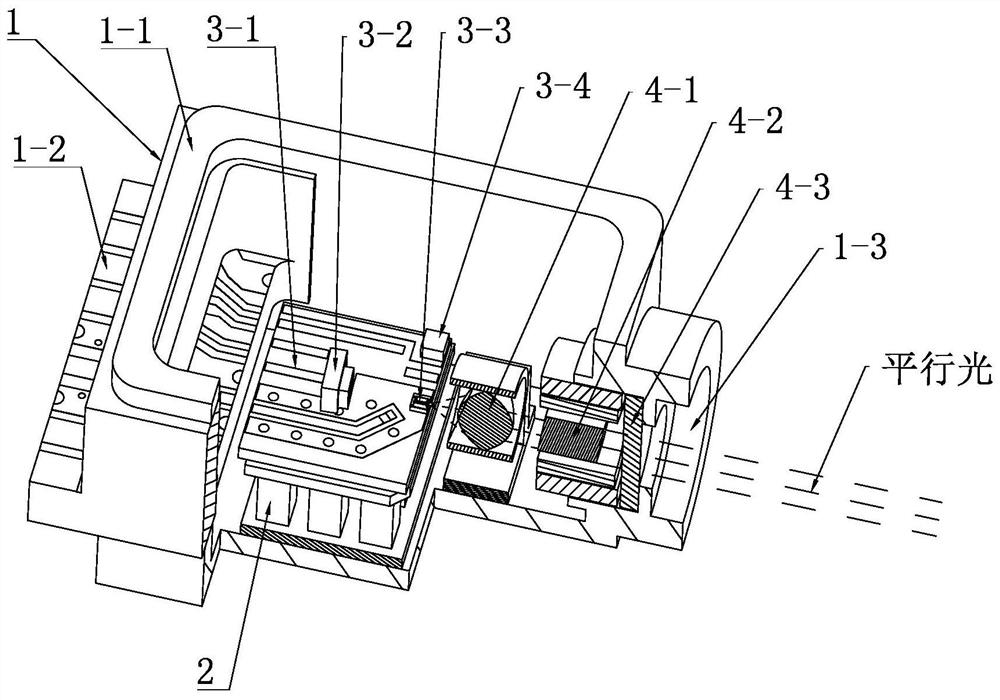
[0029] In this embodiment, the end of optical interconnection between the light-emitting component and the light-receiving component is used as the front end, wherein the light-emitting component includes a transmitting-end shell 1 with a light outlet 1-3 at the front end, and a ceramic substrate installed in the emitting-end shell. 3-1. The LD chi...


PUM


Abstract

The invention relates to an inter-board microwave optical wireless transmission system, and the system comprises a light transmitting assembly and a light receiving assembly which are used for realizing inter-board microwave optical signal transmission; the light emitting assembly comprises an emitting end tube shell, a ceramic substrate, an LD chip and a collimating lens, wherein the front end of the emitting end tube shell is provided with a light outlet, the ceramic substrate is installed in the emitting end tube shell, the LD chip is integrated on the ceramic substrate, the collimating lens is located at the front end of the LD chip, and a space isolator is arranged at the front end of the collimating lens. The light receiving assembly comprises a receiving end tube shell, a coupling lens, a substrate and a radio frequency wiring board, wherein the front end of the receiving end tube shell is provided with a light inlet, the coupling lens is installed in the receiving end tube shell, the substrate is arranged at the rear end of the coupling lens, the radio frequency wiring board is electrically connected with the substrate, and a PD chip is integrated on the substrate. By means of the technical scheme, modulation of microwave signals, optical wireless transmission and demodulation of microwave optical modulation signals can be achieved, and then transmission of the microwave optical modulation signals within the distance of 50 mm between boards is achieved.

Description

technical field [0001] The invention belongs to the technical field of inter-board wireless communication, in particular to an inter-board microwave optical wireless transmission system. Background technique [0002] The inter-board microwave optical wireless transmission system includes three functions: microwave optical modulation, microwave optical wireless transmission and microwave optical demodulation. Microwave optical modulation modulates microwave signals onto optical signals; microwave optical transmission realizes the wireless transmission function of microwave optical modulation signals ; Microwave optical demodulation demodulates the microwave signal in the received optical modulation signal. The microwave optical transmission system has the advantages of high operating frequency, wide bandwidth, transparent transmission, simple structure, high reliability, and anti-interference. It is widely used in the field of national defense, including electronic countermea...

Claims


Application Information

Patent Timeline
Patent Type & Authority Applications(China)
IPC IPC(8): H04B10/11H04B10/50H04B10/516H04B10/60
CPCH04B10/11H04B10/501H04B10/516H04B10/60
Inventor 左朋莎刘朋任欢许利伟张江帆宋春峰
Owner CHINA AVIATION OPTICAL-ELECTRICAL TECH CO LTD
Why Eureka
Try Eureka