Take-up type new energy charging pile

A charging pile and new energy technology, applied in the field of take-up new energy charging piles, can solve the problems of exposed charging guns, long charging cables, broken wires, etc.

Pending Publication Date: 2021-04-30
张书敏
View PDF8 Cites 2 Cited by
  • Summary
  • Abstract
  • Description
  • Claims
  • Application Information

AI Technical Summary

Problems solved by technology

[0004] 1. The charging gun is directly exposed and is easily damaged by man-made;
[0005] 2. The charging cable is long and often directly in contact with the ground. It is easy to cause damage to the cable for a long time, and there is a safety risk.

Method used


Image

  • Take-up type new energy charging pile
  • Take-up type new energy charging pile
  • Take-up type new energy charging pile

Examples


Embodiment 1

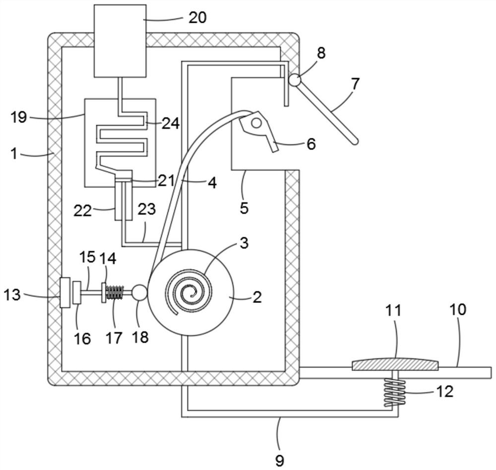
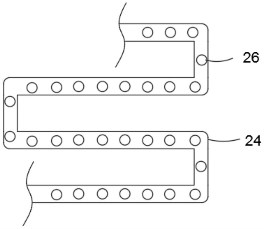
[0026] refer to Figure 1-2 , a take-up type new energy charging pile, including a pile body 1, a take-up reel 2 and a component plate 19 are installed inside the pile body 1, a heat dissipation mechanism connected to the component plate 19 is provided in the pile body 1, and the component plate 19 Including a control module and a power supply module, etc., the heat dissipation mechanism includes a water tank 20 fixedly embedded in the upper side wall of the pile body 1, and the lower side wall of the water tank 20 is connected with a multi-section and continuous cooling pipe 24 in contact with the outer wall of the component plate 19 A plurality of resistance steel balls 26 are evenly fixed on the inner wall of the cooling pipe 24, and the resistance steel balls 26 are set to slow down the flow velocity of water in the cooling pipe 24, so as to ensure that the water can reduce the heat generated on the assembly plate 19 and then flow down after sufficient absorption. The lowe...

Embodiment 2

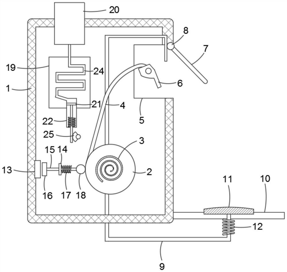
[0030] refer to image 3 , the difference from Example 1 is:

[0031]The heat dissipation mechanism includes a water tank 20 fixedly embedded in the upper side wall of the pile body 1. The lower side wall of the water tank 20 is connected with a multi-section and continuous cooling pipe 24 in contact with the outer wall of the component plate 19. The lower end of the cooling pipe 24 is connected with a suction pipe. Pipe 22, the inner wall of the suction pipe 22 slides with a piston 21, the lower side wall of the piston 21 is fixedly connected with a tooth plate, and a connecting spring is fixedly connected between the outer wall of the tooth plate and the inner bottom wall of the suction pipe 22, and the pile body 1 A motor is fixed inside, and the driving end of the motor is fixedly connected with an incomplete gear 25 that meshes with the tooth plate. The motor is connected to the output line of the pile body 1. When the pile body 1 starts to work, the motor is energized to...


PUM


Abstract

The invention discloses a take-up type new energy charging pile which comprises a pile body, a take-up reel and an assembly plate are installed in the pile body, a heat dissipation mechanism connected with the assembly plate is arranged in the pile body, a torque spring is fixedly connected between the outer wall of the take-up reel and the inner wall of the pile body, and a charging wire is wound around the take-up reel. A charging gun is connected to the end of the charging wire, a containing opening is formed in the outer wall of the pile body, the charging gun is located in the containing opening, a rotating plate is rotatably connected to the inner top wall of the containing opening through a rotating shaft, the outer wall of the rotating shaft is fixedly sleeved with a gear, and a transverse plate is fixedly connected to the outer wall of the lower end of the pile body. In the charging process, the charging wire is automatically abutted, the charging gun is prevented from being separated from the charging port, the charging wire is automatically withdrawn and wound on the take-up reel when charging work is finished, meanwhile, the rotating plate rotates downwards to protect the charging gun, damage to the charging wire and the charging gun is avoided, and the service life of a pile body part is prolonged.

Description

technical field [0001] The invention relates to the field of new energy technologies, in particular to a take-up type new energy charging pile. Background technique [0002] New energy vehicles refer to the use of unconventional vehicle fuels as power sources (or the use of conventional vehicle fuels, the use of new vehicle power devices), integrated vehicle power control and advanced technology in driving, the formation of advanced technical principles, with Vehicles with new technologies and new structures. With the limitation of conventional energy sources and the increasingly prominent environmental problems, new energy vehicles with environmental protection and renewable characteristics have attracted more and more attention from various countries. [0003] As a charging gun used in conjunction with new energy vehicles, it is widely distributed in cities for use, but the existing charging piles have the following problems during use: [0004] 1. The charging gun is dir...

Claims


Application Information

Patent Timeline
Patent Type & Authority Applications(China)
IPC IPC(8): B60L53/31B60L53/16B60L53/18B60L53/302B65H75/48
CPCB60L53/31B60L53/16B60L53/18B60L53/302B65H75/48Y02T10/70Y02T10/7072Y02T90/12Y02T90/14
Inventor 张书敏
Owner 张书敏
Why Eureka
Try Eureka