Protection device for belt conveyor

A technology of belt conveyor and protection device, applied in the direction of conveyor control device, conveyor, conveyor objects, etc., can solve the problems of conveyor belt stacking, conveyor equipment damage, flanging and other problems, so as to avoid equipment failure. Damage and injury to personnel, reduced maintenance costs, improved reliability

Pending Publication Date: 2021-04-30
HUANENG POWER INT INC
View PDF0 Cites 0 Cited by
  • Summary
  • Abstract
  • Description
  • Claims
  • Application Information

AI Technical Summary

Problems solved by technology

[0006] 1. When the belt conveyor encounters special conditions, the conveyor belt has a large flow rate during operation, and the conveyor belt has serious deviations when carrying materials and other abnormal conditions, a large amount of materials will be scattered on the return belt. , is sent to the tail of the belt conveyor, and the empty segment cleaner configured on the belt conveyor cannot clean up these materials, which will cause some materials to be involved between the conveyor belt and the tail redirecting roller. The accumulation of more and more at the tail drum, the interaction force between the conveyor belt and the tail redirection drum becomes uneven when the material is involved, and the radius of gyration of the conveyor belt is greater than the diameter of the drum, so that the conveyor belt and the belt The frame of the belt conveyor has severe friction, even deflected to one side of the roller, and flanging occurs, which will seriously damage the belt conveyor equipment;
[0007] 2. The conveyor belt has a longitudinal tear failure during operation, and the conveyed material will leak from the middle of the torn conveyor belt to the return belt, or the conveyor belt will fold up after being torn, or the conveyor belt will become narrow after tearing , unable to carry the normal material delivery volume, at this time, a large amount of material will be scattered on the return belt and sent to the tail of the belt conveyor. Due to the limited cleaning capacity of the empty end cleaner, the material is passing through the empty end cleaner. After being drawn into between the conveyor belt and the rear redirecting roller;
[0008] 3. When parts on the belt conveyor fall on the return conveyor belt, or foreign objects (such as metal objects, overhauled tools, waste, various sundries, etc.) are scattered on the return conveyor belt, due to the shape of these objects Irregularity, it is difficult for the empty section cleaning device at the tail to clean these objects out of the belt conveyor. These objects can often pass through the empty section cleaning device and be transported to the rear redirecting roller by the return conveyor belt, which can easily cause conveyor belt Damage to the equipment, resulting in failure to operate normally;
[0009] 4. There are often many equipments at the reversing drum at the tail of the belt conveyor. When the belt conveyor is running, various personnel will perform various operations there, and it may happen that personnel or tools are involved in the return belt and The situation between the reversing rollers at the tail, resulting in accidents of personal injury or equipment damage, such accidents have occurred in many places where belt conveyors are used

Method used


Image

  • Protection device for belt conveyor
  • Protection device for belt conveyor

Examples


Embodiment 1

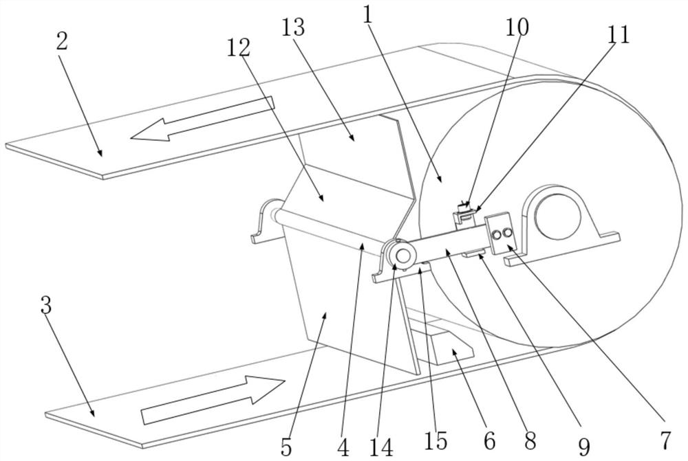
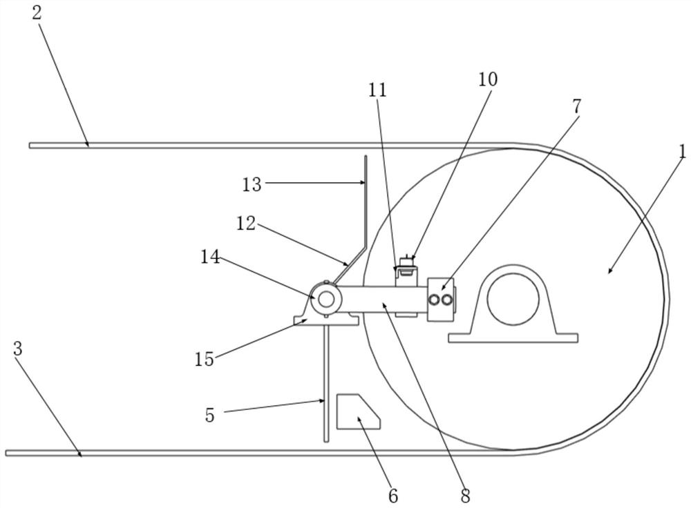
[0041] The belt conveyor includes a frame, a driving mechanism for driving the belt conveyor, a driving drum, a reversing drum 1, and a conveyor belt sleeved on the driving drum and the reversing drum 1, the bottom of the reversing drum 1 and the The conveyor belt moving in the opposite direction of material conveying is the return conveyor belt 3, and the conveyor belt on the top of the diverting drum 1 is the outgoing conveyor belt 2.

[0042] The present invention provides a kind of protection device for belt conveyor for belt conveyor, such as Figure 1~2 As shown, the protective device of the present invention is located on the return conveyor belt 3, and the protective device includes a rotating shaft 4, a foreign matter blocking plate 5 and a rotating trigger mechanism, the rotating shaft 4 is fixedly connected with the frame of the belt conveyor, and the foreign matter blocking plate 5 Vertically arranged, the top of the foreign matter blocking plate 5 is fixedly connect...

Embodiment 2

[0049] The difference between this embodiment and Embodiment 1 is that the rotation trigger mechanism specifically includes a weight block 7, a weight arm 8, a weight frame 9 and a trigger sensor 10, and one end of the weight arm 8 is fixedly connected to the rotation shaft 4 , the other end is fixedly connected with the heavy hammer block 7, the heavy hammer frame 9, the trigger sensor 10 are fixedly connected with the frame of the belt conveyor, and the bottom of the heavy hammer arm 8 conflicts with the heavy hammer frame 9.

[0050] The weight of the weight block 7 can be adjusted according to the condition of the conveyed material, the actual working conditions on site, and the specific structure of the belt conveyor, so as to improve the detection sensitivity and prevent false triggering.

[0051] In this embodiment, the trigger sensor 10 is a proximity sensor.

[0052] When the protection device of this embodiment is in use, if a foreign matter appears on the return con...

Embodiment 3

[0054] The difference between this embodiment and Embodiment 2 is that in order to prevent the heavy hammer arm 8 from oversteering and to install the trigger sensor 10, the rotating trigger mechanism also includes a sensor bracket 11 for fixing the trigger sensor 10 and limiting the rotation angle of the heavy hammer arm 8. The sensor 10 is disposed on the sensor bracket 11 .

[0055] In this embodiment, the sensor bracket 11 is L-shaped.

[0056] When in use, the heavy hammer arm 8 is in conflict with the sensor bracket 11 after rotating a certain angle around the rotating shaft 4 .


PUM


Abstract

The invention relates to a protection device for a belt conveyor. The protection device is arranged on a return conveying belt and comprises a rotating shaft, a foreign matter blocking plate and a rotation triggering mechanism, the rotating shaft is fixedly connected with a rack of the belt conveyor, the foreign matter blocking plate is vertically arranged, the top of the foreign matter blocking plate is fixedly connected with the rotating shaft, the bottom of the foreign matter blocking plate and the return stroke conveying belt are arranged in a spaced mode, the rotation triggering mechanism is fixedly connected with the rotating shaft, and during use, the foreign matter blocking plate drives the rotating shaft to rotate and drives the rotation triggering mechanism to operate. Compared with the prior art, safety protection is conducted under the conditions that large foreign matter is difficult to clean away, small foreign matter is accumulated repeatedly, and personnel injuries are prone to occurring frequently, the safety performance of the belt conveyor is effectively improved, the reliability is high, and equipment damage and personnel injuries are effectively prevented and avoided.

Description

technical field [0001] The invention relates to a protection device for a conveyor, in particular to a protection device for a belt conveyor. Background technique [0002] The belt conveyor is a common equipment for material transportation. The material falls on the receiving point at the tail of the belt conveyor, and the material is transported to the driving roller at the head through the conveyor belt. Direction, in order to achieve the role of continuous delivery. [0003] During the operation of the belt conveyor, it is inevitable that scattered materials or equipment parts and various foreign objects will fall on the return conveyor belt and move towards the rear redirection roller. Although the belt conveyor is equipped with an empty section cleaning device, There will always be some materials or foreign matter that will pass over the empty section cleaner, and will eventually be drawn between the rear redirection roller and the conveyor belt, causing the conveyor b...

Claims


Application Information

Patent Timeline
Patent Type & Authority Applications(China)
IPC IPC(8): B65G43/08B65G43/02B65G43/00
CPCB65G43/08B65G43/02B65G43/00B65G2207/40B65G21/00B65G45/12B65G2203/0266
Inventor 张晓
Owner HUANENG POWER INT INC
Why Eureka
Try Eureka