Led display tape sticking machine and its working method

A technology of LED display screen and sticking tape, applied in the direction of cleaning method using tools, chemical instruments and methods, cleaning methods and utensils, etc., can solve problems such as poor efficiency and trouble

Active Publication Date: 2022-07-05
深圳乐视商显科技有限公司
View PDF6 Cites 0 Cited by
  • Summary
  • Abstract
  • Description
  • Claims
  • Application Information

AI Technical Summary

Problems solved by technology

The inventor found that it is necessary to pre-coat the sealant at the installation place of the tape before the tape is attached, which can further improve the level of sealing and safety; but the sealant application and tape application in the existing operation are two independent processes. Generally, the sealant is manually applied first, and then the tape is applied manually. This is more troublesome, less efficient, and there is still room for improvement in the actual effect.

Method used


Image

  • Led display tape sticking machine and its working method
  • Led display tape sticking machine and its working method
  • Led display tape sticking machine and its working method

Examples


Embodiment 1

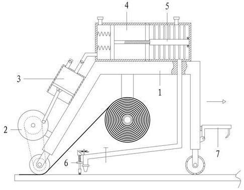
[0061] Referring to the drawings, the tape machine for LED display screen includes a frame assembly 1, a transmission assembly 109, an inflatable assembly 3 and a gluing assembly 4;

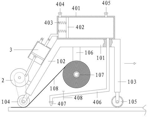
[0062] The frame assembly 1 includes a top plate 101, a left leg 102, a right leg 103, a pressing roller 104, a cleaning roller 105, a fixing rod 106 and a mounting shaft 107; the left end of the top plate 101 is connected with a left leg 102, and the right end is connected with a right support Leg 103; the bottom end of the left leg 102 is equipped with a pressing roller 104, and the bottom end of the right leg 103 is equipped with a cleaning roller 105; a fixing rod 106 is connected below the top plate 101, and an installation shaft 107 is connected to the front side of the fixing plate, and the installation shaft 107 is used for Tape 108 for wrapping into a plate;

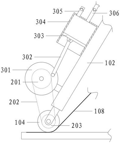
[0063] The left leg 102 is provided with an inflatable assembly 3 , which cooperates with the pressing roller 104 through a trans...

Embodiment 2

[0065] Referring to the drawings, the tape machine for LED display screen includes a frame assembly 1, a transmission assembly 109, an inflatable assembly 3 and a gluing assembly 4;

[0066] The frame assembly 1 includes a top plate 101, a left leg 102, a right leg 103, a pressing roller 104, a cleaning roller 105, a fixing rod 106 and a mounting shaft 107; the left end of the top plate 101 is connected with a left leg 102, and the right end is connected with a right support Leg 103; the bottom end of the left leg 102 is equipped with a pressing roller 104, and the bottom end of the right leg 103 is equipped with a cleaning roller 105; a fixing rod 106 is connected below the top plate 101, and an installation shaft 107 is connected to the front side of the fixing plate, and the installation shaft 107 is used for Tape 108 for wrapping into a disc;

[0067] The left leg 102 is provided with an inflatable assembly 3 , which cooperates with the pressing roller 104 through a transm...

Embodiment 3

[0082] In the above-mentioned embodiment, the tape reel is directly sleeved on the installation shaft 107, which is easy to fall off during use. Therefore, on the basis of Embodiment 2, a fixing assembly 9 is also provided;

[0083] The fixing assembly 9 includes an installation groove 901, a second-class wedge block 902, a spring 903, a limit rope 904 and a limit ring 905;

[0084] The rear section of the installation shaft 107 is fixedly connected to the limit ring 905; the front section of the installation shaft 107 is symmetrically provided with an installation groove 901, and a second-class wedge-shaped block 902 is slidably connected in the installation groove 901, and the inclined surface of the second-class wedge-shaped block 902 faces the front side; The wedge block 902 and the inner bottom of the installation groove 901 are connected by a spring 903 and a limit rope 904 .

[0085] Specifically, the spring 903 makes the second-class wedge-shaped block 902 always tend ...


PUM


Abstract

The invention relates to the technical field of LED display screen sticking, and relates to a tape sticking machine for LED display screen and a working method; when the machine moves to the right, a cleaning roller first cleans the LED display screen; The cooperation of the transmission belt makes the turntable rotate synchronously, and the turntable drives the push-pull rod to move the No. 1 piston plate up and down in the air cylinder. With the cooperation of two one-way valves, the air cylinder is inflated to the rubber barrel; the left side of the No. 2 piston plate is continuously inflated and the pressure increases. large, so that the No. 2 piston plate moves to the right and pushes the sealant to flow into the rubber discharge pipe and discharge it from the glue discharge head, and then apply it to the cleaned LED display; the pressure roller presses the sticking end of the tape, so that the tape reel is on the right When the machine moves, it rotates and unwinds by itself, and sticks the tape on the LED display screen that has been coated with sealant; in this way, with the movement of the machine, the operations of cleaning, gluing and sticking the tape on the display screen are automatically completed, which is fast and convenient.

Description

technical field [0001] The invention relates to the technical field of LED display screen sticking, and relates to an LED display screen sticking tape machine and a working method. Background technique [0002] LED display (LED display) is a kind of flat panel display, which consists of small LED module panels, and is used to display various information such as text, images, and videos. [0003] LED, namely light emitting diode (light emitting diode abbreviation). It is a display method by controlling semiconductor light-emitting diodes. It is a diode made of gallium (Ga) and arsenic (As), phosphorus (P), nitrogen (N), and indium (In) compounds. When electrons and holes It can radiate visible light when recombined, so it can be used to make light-emitting diodes. [0004] Used as indicator lights in circuits and instruments, or composed of text or digital displays. Gallium arsenide phosphide diodes emit red light, gallium phosphide diodes emit green light, silicon carbide...

Claims


Application Information

Patent Timeline
Patent Type & Authority Patents(China)
IPC IPC(8): B65H37/04B08B1/02B01F27/70B01F35/71B01F101/36
CPCB65H37/04B08B1/02B01F27/70B01F35/71B01F35/754251B01F35/75
Inventor 崔玲
Owner 深圳乐视商显科技有限公司
Why Eureka
Try Eureka