
Goaf site high-speed railway subgrade settlement monitoring device and observation method

A technology for high-speed railway and settlement monitoring, which is applied in the fields of on-site foundation soil survey, railway signal and safety, and infrastructure engineering. , the planning and development is convenient, the effect of small launch angle

Pending Publication Date: 2021-04-30
HENAN POLYTECHNIC UNIV
View PDF0 Cites 3 Cited by
  • Summary
  • Abstract
  • Description
  • Claims
  • Application Information

AI Technical Summary

Problems solved by technology

However, due to the existence of many gobs in major provinces of underground resource mining, the planning and popularization of high-speed railways has become difficult, which seriously lags behind the development of my country's transportation industry
The high-speed train unit is extremely sensitive to the uneven subsidence of the subgrade. The current track geometric state detector (track inspection trolley) can only monitor the rails during the railway operation window. There are many conditions and require a lot of labor. Although it can guarantee a certain accuracy but not efficient
The uneven settlement of the roadbed is a great threat to the safe operation of the EMU.

Method used


Image

  • Goaf site high-speed railway subgrade settlement monitoring device and observation method
  • Goaf site high-speed railway subgrade settlement monitoring device and observation method
  • Goaf site high-speed railway subgrade settlement monitoring device and observation method

Examples


Embodiment Construction

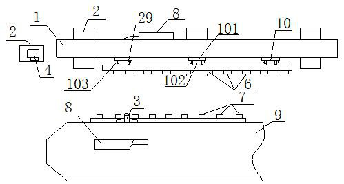
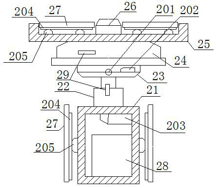
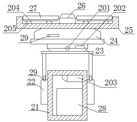
[0029] Such as figure 1- As shown in -3, a subsidence monitoring device for a high-speed railway in a goaf site, including a laser signal receiving wall 1, an automatic level adjustment platform 2, a laser emission port A3, a laser emission port B4, a circuit receiving module board 5, and a laser receiver M6, laser receiver N7 and microcomputer receiving control system 8, the laser signal receiving wall 1 is a wall structure that is transversely rectangular and distributed parallel to the railway axis. Connection, there are two circuit receiving module boards 5, and they are all electrically connected to the microcomputer receiving control system 8, one of which is embedded in the front end of the laser signal receiving wall 1, and is parallel to the horizontal plane, and one of the circuit receiving module boards 5 and the laser receiver M6 The laser receiver M6 is electrically connected to the circuit receiving module board 5, and the optical axis of the laser receiver M6 is...


PUM

PropertyMeasurementUnit
Widthaaaaaaaaaa

Abstract

The invention relates to a goaf site high-speed railway subgrade settlement monitoring device. The device comprises a laser signal receiving wall, an automatic level adjusting platform, a laser transmitting port A, a laser transmitting port B, a circuit receiving module board, a laser receiver M and a laser receiver N, wherein a microcomputer receiving control system and the laser receiver M are embedded in the front end face of the laser signal receiving wall; the laser transmitting port B is connected with the ground plane through the automatic level adjusting platform; and the laser transmitting port A, the laser receiver N and the circuit receiving module board are all embedded in the side surface of a train. The settlement observation method comprises the five steps of subgrade observation equipment positioning, laser signal receiving wall construction, train body observation structure assembling, settlement observation and settlement judgment. According to the invention, the purpose of accurate detection of settlement monitoring of a goaf site subgrade is realized on the premise of relatively low cost; and meanwhile, real-time judgment and early warning on an operation state of the train under the condition of uneven settlement in a comparison site are realized.

Description

technical field [0001] The invention relates to a subsidence monitoring device and an observation method of a high-speed railway subgrade in a goaf site, belonging to the technical field of engineering detection. Background technique [0002] my country has abundant underground resources, and the area of ​​ground subsidence caused by mining has continued to expand in the past few decades. With the rapid development of the economy, my country's high-speed railway network has gradually formed a scale of "four vertical and four horizontal" in recent years. With its amazing development speed and excellent strength, my country's high-speed railway has won high recognition from the international community. However, due to the existence of many mined-out areas in major provinces of underground resource mining, the planning and popularization of high-speed railways has become difficult, which seriously lags behind the development of my country's transportation industry. The high-sp...

Claims


Application Information

Patent Timeline
IPC IPC(8): E02D1/00B61L23/04
CPCB61L23/048E02D1/00
Inventor 宋明伟张文志邹友峰蔡来良任筱芳柴华彬柳广春丁来中
Owner HENAN POLYTECHNIC UNIV
Learn More