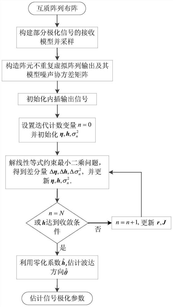
Co-prime array partial polarization signal parameter estimation method based on zero interpolation
A polarization signal and parameter estimation technology, which is applied to the direction of the direction determination device, the direction finder using radio waves, the radio wave direction/bias determination system, etc., which can solve the problem of incomplete array information extraction and insufficient utilization of degrees of freedom. and other problems, to achieve the effect of increasing the number, improving the accuracy of the estimation, and reducing the mutual coupling of the array elements.
- Summary
- Abstract
- Description
- Claims
- Application Information
AI Technical Summary
Problems solved by technology
Method used
Image
Examples
Embodiment 1
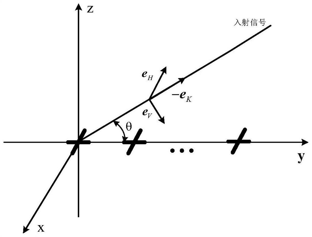
[0177] Take the extended coprime array, the number of elements of the two sub-arrays is M 1 = 2, M 2 =5, that is, a total of 2M 1 +M 2 -1=8 cross-pole antenna elements for signal reception. Assume that the angles of the 12 incident signals are uniformly distributed between [30, 150], the polarization pointing angles are uniformly distributed between [-π / 3,π / 3], and the polarization ellipticity angles are uniformly distributed in [-π / 5 ,π / 5], the signal polarization is uniformly set to 0.8. The signal-to-noise ratio is set to 20dB, the number of sampling snapshots is 500, the maximum number of iterations is N=100, and the convergence threshold ζ=10 -6 .
[0178] Run the program 10 times to get its spatial power spectrum graph such as Figure 4As shown, the dotted line in the figure represents the real angle of the incident signal. This embodiment can effectively distinguish these 12 signals. Since the number of signals 12 is greater than the number of sensors 8 and the ...
Embodiment 2
[0183] Set the number of subarrays of two extended coprime arrays to M 1 = 2, M 2 =5, a total of 8 physical array elements. Assume that 10 far-field narrowband partially polarized signals equally distributed in [30, 150] are incident on the array. The signal-to-noise ratio is set to 20dB, the number of snapshots is scanned from 50 to 500, and the number of Monte Carlo experiments is 500, and other parameters are the same as in Embodiment 1.
[0184] Figure 5 For using the method of the present invention and the simulation results of the orthogonal subspace method and the quaternion method. It can be seen from the figure that the method of the present invention achieves the minimum root mean square error at each snapshot number. This is because the orthogonal subspace method and the quaternion method only intercept the continuous part of the virtual array, and the noise covariance of the array model is not considered. In particular, the quaternion method has the worst est...
Embodiment 3
[0186] Assuming that 10 far-field narrowband partially polarized signals evenly distributed in [30, 150] are incident on the same array as in Example 1, the signal-to-noise ratio is set to scan from -10dB to 20dB, and the number of Monte Carlo experiments is 500 times. All the other parameters are the same as in Example 1.
[0187] Figure 6 For using the method of the present invention and the simulation results of the orthogonal subspace method and the quaternion method. It can be seen from the figure that the method of the present invention achieves the minimum root mean square error at each signal-to-noise ratio. The quaternion method has the worst estimation effect due to the restriction that the horizontal and vertical signal powers are equal.
PUM
 Abstract
Description
Claims
Application Information
 - R&D
- Intellectual Property
- Life Sciences
- Materials
- Tech Scout
- Unparalleled Data Quality
- Higher Quality Content
- 60% Fewer Hallucinations
Browse by: Latest US Patents, China's latest patents, Technical Efficacy Thesaurus, Application Domain, Technology Topic, Popular Technical Reports.
© 2025 PatSnap. All rights reserved.Legal|Privacy policy|Modern Slavery Act Transparency Statement|Sitemap|About US| Contact US: help@patsnap.com


