Underground light guide pipe with disaster relief guiding function

A technology of light guide and function, applied in the field of light guide, can solve the problems of poor ventilation environment, affecting the lighting effect of the light guide, and not having fire guidance, etc., and achieve the effect of reducing the content of smoke

Inactive Publication Date: 2021-04-30
李未成
View PDF3 Cites 0 Cited by
  • Summary
  • Abstract
  • Description
  • Claims
  • Application Information

AI Technical Summary

Problems solved by technology

[0003] Due to the poor ventilation environment underground, when a fire breaks out underground, the smoke generated by the fire will accumulate underground, thereby affecting the lighting effect of the light guide tube. Guidance in the event of a fire, resulting in limited use of light pipes

Method used


Image

  • Underground light guide pipe with disaster relief guiding function
  • Underground light guide pipe with disaster relief guiding function
  • Underground light guide pipe with disaster relief guiding function

Examples


Embodiment 1

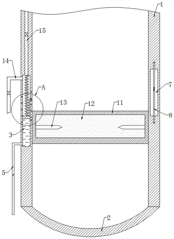
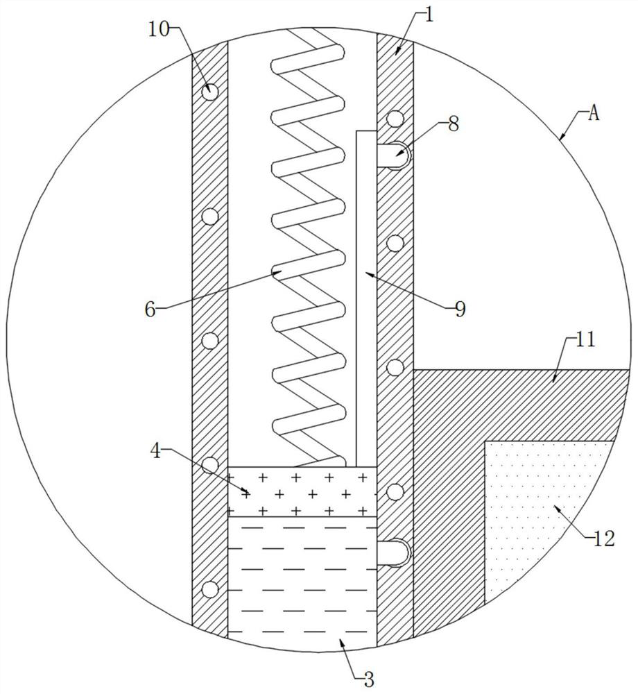
[0023] refer to Figure 1-2 , an underground light guide pipe with disaster relief guidance function, comprising a pipe body 1, a diffuser 2 is fixedly connected to the lower end of the pipe body 1, a heat absorption chamber 3 is opened on the side wall of the pipe body 1, and the inner wall of the heat absorption chamber 3 is sealed and slidably connected There is a magnetic plate 4, the upper end of the magnetic plate 4 is elastically connected to the top of the heat-absorbing chamber 3 through a spring 6, and the upper part of the inner wall of the heat-absorbing chamber 3 is connected to the lower part of the inner wall of the heat-absorbing chamber 3 through a one-way return pipe 8. It should be noted that the one-way The return pipe 8 only allows the gaseous evaporation liquid to flow from above the inner wall of the heat-absorbing chamber 3 to below the inner wall of the heat-absorbing chamber 3 .

[0024] The upper end of the magnetic plate 4 is fixedly connected with ...

Embodiment 2

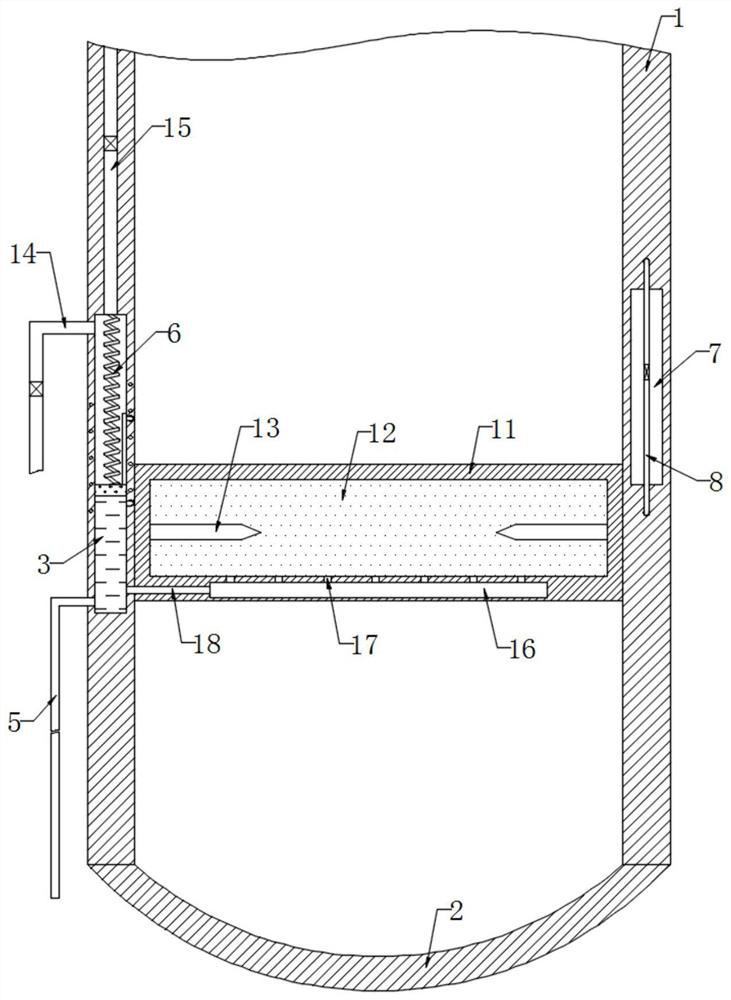
[0032] refer to image 3 , different from Embodiment 1, the bottom of the light-emitting chamber 12 is provided with a water storage chamber 16, and the top of the water storage chamber 16 is provided with a plurality of through holes 17, and the inner wall of the water storage chamber 16 connects with the inner wall of the heat-absorbing chamber 3 Link below.

[0033] In this embodiment, the heat conduction sheet 18 can transmit the temperature in the evaporating liquid to the water storage chamber 16. After the temperature in the evaporating liquid rises, the temperature of the water in the water storage chamber 16 rises at this time, and then the water in the unit The amount of evaporation within the time increases, so that water vapor enters the luminous cavity 12 through the through hole 17, thereby increasing the humidity of the gas in the luminous cavity 12, making the gas easier to be ionized, that is, the minimum breakdown voltage of the gas is reduced, and it is easi...


PUM


Abstract

The invention discloses an underground light guide pipe with a disaster relief guiding function. The underground light guide pipe with the disaster relief guiding function comprises a pipe body, wherein a diffuser is fixedly connected to the lower end of the pipe body, a heat absorption cavity is formed in the side wall of the pipe body, a magnetic plate is slidably connected to the inner wall of the heat absorption cavity in a sealed mode, the upper end of the magnetic plate is elastically connected with the inner top part of the heat absorption cavity through a spring, the upper portion of the inner wall of the heat absorption cavity is connected with the lower portion of the inner wall of the heat absorption cavity through a one-way backflow pipe, a partition plate is fixedly connected to the upper end of the magnetic plate, a spiral coil is embedded in the inner wall of the heat absorption cavity, and a fixing plate is fixedly connected to the inner wall of the pipe body. According to the underground light guide pipe, current is generated through induction current and accumulated on two discharge needles respectively, so that tips of the two discharge needles accumulate a large number of positive and negative charges respectively, when charges accumulated at the tips of the discharge needles reach a certain degree, the current is released, neon gas discontinuously emits orange red light after being broken down, the indication effect can be effectively achieved, and then safety indication is carried out on underground people.

Description

technical field [0001] The invention relates to the technical field of light guide pipes, in particular to an underground light guide pipe with disaster relief guidance function. Background technique [0002] As a non-electric lighting system, the light pipe can use sunlight for indoor lighting during the day, and the diffuser at the bottom of the light pipe can evenly and efficiently irradiate natural light to any place that needs light. In complex environments such as basements, due to the high cost of laying circuits, light pipes are usually used for lighting. [0003] Due to the poor ventilation environment underground, when a fire breaks out underground, the smoke generated by the fire will accumulate underground, thereby affecting the lighting effect of the light guide tube. Guidance in the event of a fire causes limitations in the use of light pipes. [0004] Based on this, the present invention proposes an underground light pipe with disaster relief guidance functi...

Claims


Application Information

Patent Timeline
Patent Type & Authority Applications(China)
IPC IPC(8): H01T1/20
CPCH01T1/20
Inventor 李未成徐云飞
Owner 李未成
Why Eureka
Try Eureka