Pile casing device for brine stratum mucky soil cast-in-place pile construction

A technology of silty soil and cast-in-situ piles, which is applied in sheet pile walls, foundation structure engineering, construction, etc., can solve problems such as excessive sediment, inconvenient construction, and low bearing capacity, and achieve the effect of eliminating pollution and ensuring construction effects

Active Publication Date: 2021-05-04
SHANDONG JIAOTONG UNIV
View PDF7 Cites 3 Cited by
  • Summary
  • Abstract
  • Description
  • Claims
  • Application Information

AI Technical Summary

Problems solved by technology

[0006] The object of the present invention is to provide a kind of brine formation sludge in order to overcome the problems of collapsed holes, over-thick sediment, low bearing capacity and inconvenient construction in the prior art A casing device for the construction of cast-in-place piles in silty soil, the casing device for the construction of silty soil in brine formations has the effects of preventing collapse holes, sediment and cracking

Method used


Image

  • Pile casing device for brine stratum mucky soil cast-in-place pile construction
  • Pile casing device for brine stratum mucky soil cast-in-place pile construction
  • Pile casing device for brine stratum mucky soil cast-in-place pile construction

Examples


Embodiment 1

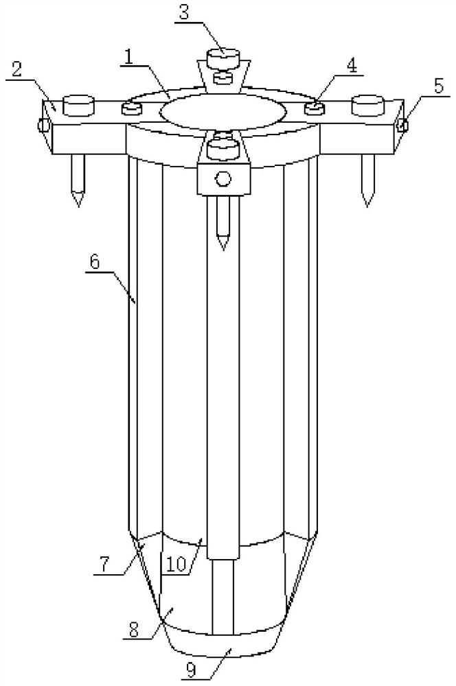
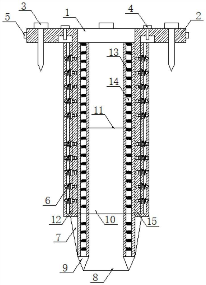
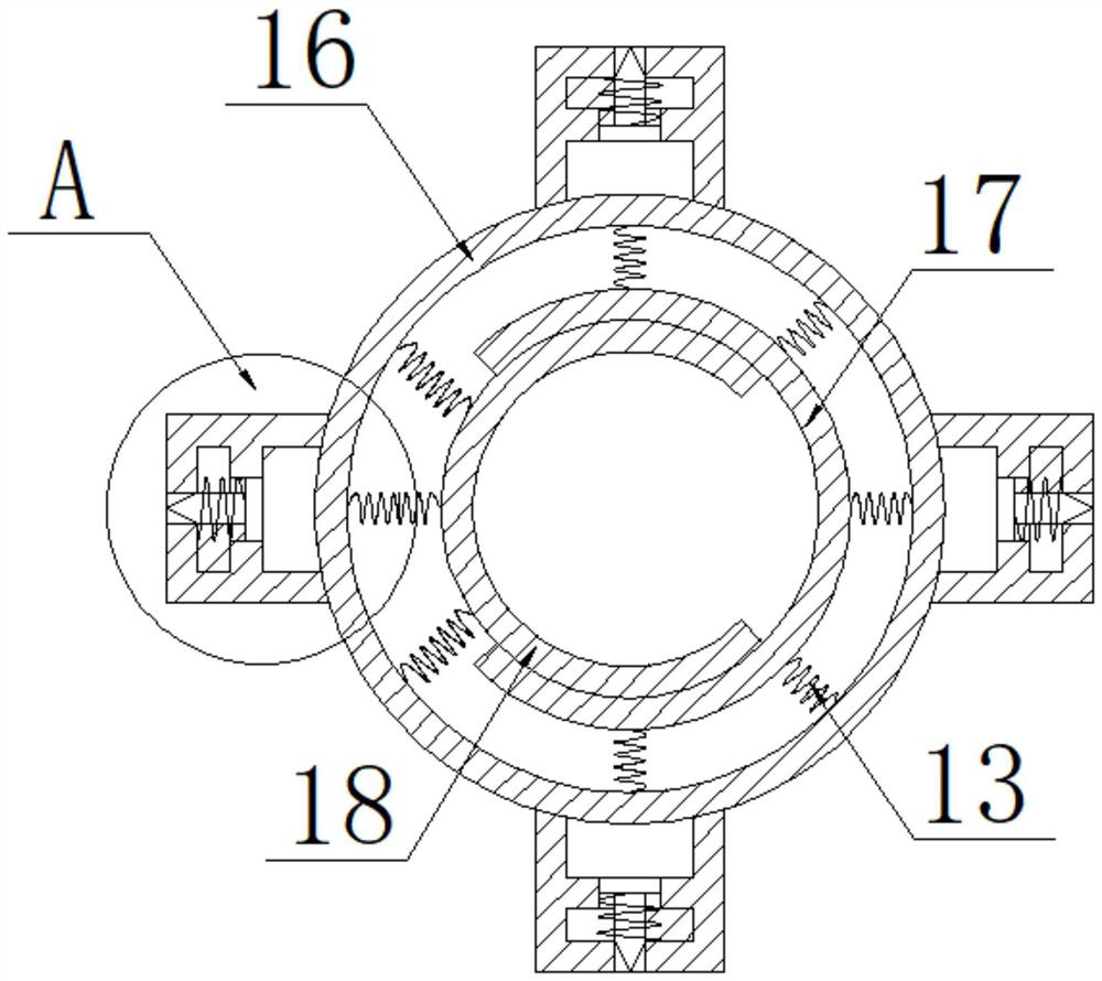
[0038] see Figure 1-8 , the present invention provides a technical solution: a casing device for the construction of silty soil grouting piles in brine formations, comprising a casing head 1, a fixed horizontal plate 2 and an outer casing body 16, the upper surface of the casing head 1 is fixedly connected with The horizontal plate 2 is fixed, and the lower surface of the casing head 1 is fixedly connected with an outer casing 16, and the outer surface of the outer casing 16 is fixedly provided with reinforcing ribs 6, four of which are arranged, and the outer surface of one side of the reinforcing ribs 6 is fixed A plurality of first through holes 19 are provided, and one side of the first through hole 19 is fixed with a partition plate 12, and a plurality of second through holes 22 are provided on the partition plate 12, and the second through hole 22 is in the same position as the first through hole 19. Correspondingly arranged, one side of the dividing plate 12 is fixedly...

Embodiment 2

[0046] see Figure 1-8 , the present invention provides a technical solution: a casing device for the construction of silty soil grouting piles in brine formations, comprising a casing head 1, a fixed horizontal plate 2 and an outer casing body 16, the upper surface of the casing head 1 is fixedly connected with The horizontal plate 2 is fixed, and the lower surface of the casing head 1 is fixedly connected with an outer casing 16, and the outer surface of the outer casing 16 is fixedly provided with reinforcing ribs 6, four of which are arranged, and the outer surface of one side of the reinforcing ribs 6 is fixed A plurality of first through holes 19 are provided, and one side of the first through hole 19 is fixed with a partition plate 12, and a plurality of second through holes 22 are provided on the partition plate 12, and the second through hole 22 is in the same position as the first through hole 19. Correspondingly arranged, one side of the dividing plate 12 is fixedly...


PUM


Abstract

The invention discloses a pile casing device for brine stratum mucky soil cast-in-place pile construction, which comprises a pile casing head, a fixed transverse plate and an outer pile casing body, the upper surface of the pile casing head is fixedly connected with the fixed transverse plate, the lower surface of the pile casing head is fixedly connected with the outer pile casing body, and reinforcing ribs are fixedly arranged on the outer surface of the outer pile casing body. The number of the reinforcing ribs is four, a plurality of first through holes are fixedly formed in the outer surfaces of one sides of the reinforcing ribs, a partition plate is fixedly arranged on one sides of the first through holes, a plurality of second through holes are formed in the partition plate, and the second through holes correspond to the first through holes in position. The outer pile casing body, the first inner pile casing body and the second inner pile casing body are arranged, so that the phenomena that a pile body deflects, a pile hole shrinks, collapses and even cannot be formed easily in the drilling process when a sludge layer is thick or located in a middle layer are effectively avoided, a mud wall protection process is avoided, and pollution to underground soil and water is completely eradicated.

Description

technical field [0001] The invention relates to the technical field of cast-in-situ pile construction technology, in particular to a casing device for construction of cast-in-place piles in muddy soil in brine formations. Background technique [0002] Cast-in-place pile is a kind of pile made by forming holes in place and pouring concrete or reinforced concrete. Commonly used ones are: (1) Bored cast-in-place piles: Use auger drilling rigs, submersible drilling rigs, etc. to pour concrete into holes on the spot to form piles. There is no vibration and no soil squeezing during construction, but the settlement of the piles is slightly larger. The auger drilling rig is suitable for cohesive soil, sandy soil and artificial filling soil above the groundwater level. The drilled soil block rises along the helical blade on the drill pipe and is discharged out of the hole. The hole diameter is about 300mm, and the drilling depth is 8-12m. Soil quality and water content to select dri...

Claims


Application Information

Patent Timeline
Patent Type & Authority Applications(China)
IPC IPC(8): E02D5/66E02D5/38
CPCE02D5/665E02D5/38
Inventor 孙超群白松王彦威崔伟周颖
Owner SHANDONG JIAOTONG UNIV
Why Eureka
Try Eureka