Novel magnetorheological damper and vehicle smoothness control method

A technology of magneto-rheological shock absorbers and shock absorbers, applied in the direction of shock absorbers, springs/shock absorbers, chemical instruments and methods, etc., can solve the problem of poor shock absorption performance, insufficient consideration, and only applicable to specific industries. To reduce the impact of damping force, prevent the magneto-rheological effect from deteriorating or degrading, and improve ride comfort and handling stability

Active Publication Date: 2021-05-04
WUHAN UNIV OF TECH
View PDF11 Cites 0 Cited by
  • Summary
  • Abstract
  • Description
  • Claims
  • Application Information

AI Technical Summary

Problems solved by technology

[0003] Since the engine and other components of most vehicles are placed at the front end, resulting in the center of gravity of the vehicle, the damping coefficient of the front and rear magneto-rheological shock absorbers is required to be larger in the front and smaller in the rear. For this, there have been designs to drill holes in the piston to reduce the damping coefficient. The damping coefficient of the rear magnetorheological shock absorber is small, but its shock absorption performance becomes worse when the position of the center of gravity of the vehicle changes
Moreover, the damping coefficients of the magnetorheological shock absorbers designed above are all fixed. Since the road surface changes during the driving process of the vehicle, the damping coefficients of shock absorbers required for different road vehicles are not the same. When the vibrator is matched with the vehicle suspension, most of them are only suitable for specific working conditions
The impact of the vehicle on different road surfaces, different center of gravity distribution (when carrying passengers and cargo in the trunk, etc.) and shock absorbers under different working conditions is not fully considered on the ride comfort of the vehicle

Method used


Image

  • Novel magnetorheological damper and vehicle smoothness control method
  • Novel magnetorheological damper and vehicle smoothness control method
  • Novel magnetorheological damper and vehicle smoothness control method

Examples


Embodiment Construction

[0031] The following will clearly and completely describe the technical solutions in the embodiments of the present invention with reference to the drawings in the embodiments of the present invention.

[0032] In describing the present invention, it should be understood that the terms "center", "longitudinal", "transverse", "upper", "lower", "front", "rear", "left", "right", " The orientations or positional relationships indicated by "vertical", "horizontal", "top", "bottom", "inner" and "outer" are based on the orientations or positional relationships shown in the drawings, and are only for the convenience of describing the present invention and Simplified descriptions, rather than indicating or implying that the device or element referred to must have a particular orientation, be constructed and operate in a particular orientation, and thus should not be construed as limiting the invention. In addition, the terms "first", "second" and so on are used for descriptive purposes...


PUM


Abstract

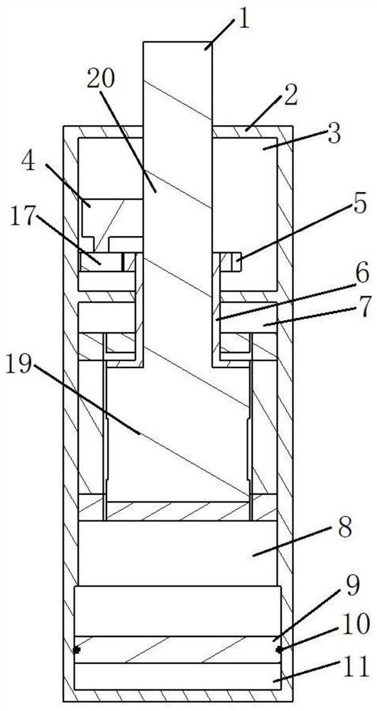
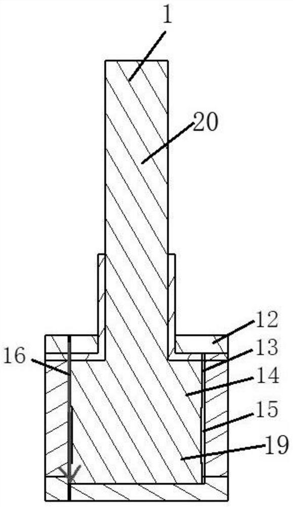
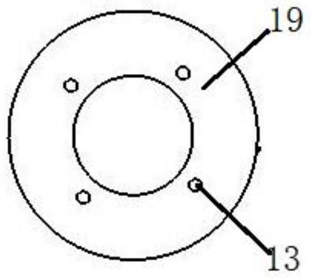
The invention discloses a novel magnetorheological damper and a vehicle smoothness control method. The novel magnetorheological damper comprises a working cylinder barrel, a piston, a flow blocking device and magnetorheological fluid, a piston cavity and a motor cavity which are adjacent to each other are formed in the working cylinder barrel, the piston comprises a piston head and a piston rod, the piston head is arranged in the piston cavity, and a plurality of first bypass holes are distributed in the piston head. The bottom of the piston rod is fixed to the piston head, a flow blocking device sleeves the piston rod and can move up and down along with the piston, a transmission mechanism capable of driving the flow blocking device to rotate relative to the piston is arranged in the motor cavity, a plurality of areas are distributed on the flow blocking device, and a set of second bypass holes are formed in each area. One set of second bypass holes at least comprise one second bypass hole, the transmission mechanism drives the flow blocking device to rotate relative to the piston, the number of aligned first bypass holes and the second bypass holes can be changed, the magnetorheological fluid is arranged in the piston cavity, and the smoothness of a vehicle under different load conditions and different road conditions is improved.

Description

technical field [0001] The invention relates to the technical field of automobile NVH, in particular to a novel magneto-rheological shock absorber and a vehicle ride comfort control method. Background technique [0002] When the car is running, the suspension system vibrates due to the excitation of the road surface. In order to improve the ride comfort of the car, a shock absorber is installed in the suspension in parallel with the elastic element. At present, automobile shock absorbers are divided into passive shock absorbers, active shock absorbers and semi-active shock absorbers. Passive shock absorbers are difficult to adapt to different roads and usage conditions due to non-adjustable parameters such as stiffness and damping. Although the active shock absorber can adapt to different roads and usage conditions, its device is complicated, the technical requirements are high, and the price is high. Therefore, the semi-active shock absorber with relatively simple manufac...

Claims


Application Information

Patent Timeline
Patent Type & Authority Applications(China)
IPC IPC(8): F16F15/023F16F15/03F16F15/027F16F9/53F16F9/32F16F9/34F16F9/36F16F9/50B01D53/26
CPCF16F15/0235F16F15/03F16F15/023F16F15/027F16F15/002F16F9/535F16F9/3207F16F9/34F16F9/368F16F9/50B01D53/261
Inventor 刘志恩安宏杰彭可挥卢炽华宋伟志李永超颜伏伍侯献军
Owner WUHAN UNIV OF TECH
Why Eureka
Try Eureka