Efficient heat exchanger

A heat exchanger, high-efficiency technology, applied in the direction of indirect heat exchangers, heat exchanger shells, heat exchange equipment, etc., can solve the problems of short contact time, low heat exchange efficiency, small temperature difference, etc., to increase heat exchange methods, Improve heat transfer efficiency, the effect of high-efficiency heat exchangers

Active Publication Date: 2021-05-04
山东中农嘉吉环保科技有限公司
View PDF4 Cites 1 Cited by
  • Summary
  • Abstract
  • Description
  • Claims
  • Application Information

AI Technical Summary

Problems solved by technology

[0004] The purpose of the present invention is to provide a high-efficiency heat exchanger, which solves the problem of low heat exchange efficiency caused by the short contact time of the two fluids and the small temperature difference in the heat exchanger in the prior art

Method used


Image

  • Efficient heat exchanger
  • Efficient heat exchanger
  • Efficient heat exchanger

Examples


Embodiment 1

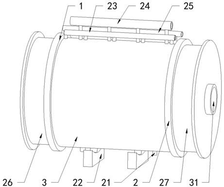
[0027]ReferFigure 1-5 A highly efficient heat exchanger, including the feed baffle 1 and the discharge baffle 2, respectively, on both faces of the intake barrel 26 and the discharge barrel 27, the feed barrel 26, and the discharge barrel 27, respectively. The inner layer fixing tub 5, sandwich fixing bucket 4 and outer fixing bucket 3, laminated bucket 4 and outer layer fixing bucket 3, the inner layer fixing bucket 5 is sequentially fixed. The inner heat exchange chamber 8, the inner fixed tub 5 is formed between the sandwich fixing tub 4, and the outer layer heat exchange chamber 6 is formed between the sandwich fixing tub 4 and the outer layer fixing tub 3, the outer heat exchange chamber 6 The first heat exchange chamber 32 that is not connected to each other is provided along the axial center line, and there is a plurality of seconds along the inner heat exchange chamber 8 in the axial center line 32 corresponding to the plurality of first heat exchange chambers 32. The heat e...

Embodiment 2

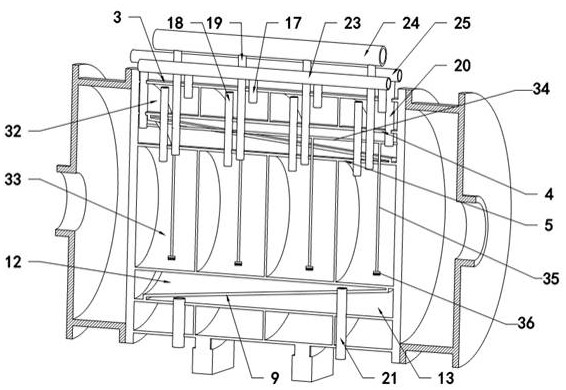
[0036]In the process of carrying out the invention, after the A solution filled with the first heat exchange chamber 32, the second vent tube 18 flows into the second heat exchange chamber 33, and after the second heat exchange chamber 33 is filled, Finally, the heat exchanger is discharged from the third vent tube 19, and the a solution having a lower temperature first enters the bottom of the second heat exchange chamber 33, exchanged heat with the B solution bottom at the bottom of the second heat exchange chamber, and then A solution absorbs heat. The temperature rises, exchange heat from the B solution above the second heat exchange chamber 33 during the rise in the rising. In this process, when the temperature is different from the temperature, the thermal A solution is mixed in the second heat exchange chamber 33, since the solution itself, the temperature high a solution increases to the upper, low temperature portion a solution At the bottom, the amount of heat exchanged in...


PUM


Abstract

The invention relates to an efficient heat exchanger, and solves the problem of low heat exchange efficiency caused by short contact time and small temperature difference of two fluids in a heat exchanger in the prior art. The efficient heat exchanger comprises a feeding barrel and a discharging barrel, and a feeding baffle and a discharging baffle are installed on the two opposite faces of the feeding barrel and the discharging barrel respectively. According to the efficient heat exchanger, the heat exchange effect of a solution B after passing through a plurality of second heat exchange cavities in an inner-layer heat exchange cavity is larger than the heat exchange effect of the solution B directly through a communicated solution A, the heat exchange effect of an outer-layer heat exchange cavity is larger than the heat exchange effect of the inner-layer heat exchange cavity, and therefore after passing through the inner-layer heat exchange cavity, the solution B is subjected to secondary heat exchange through heat exchange air in an air cavity, and then the solution B enters the outer-layer heat exchange cavity to enhance heat exchange, so that the sufficient heat exchange temperature difference between the solution A and the solution B is ensured, the heat exchange mode of air heat exchange is increased, the heat exchange receiving time of the solution B is prolonged, and the efficient heat exchanger is realized.

Description

Technical field[0001]The present invention relates to the field of heat exchanger, and more particularly to a highly efficient heat exchanger.Background technique[0002]Chemical production heat exchanger is used to interchange the heat of the A fluid and B fluid, but the existing ruthelet heat exchanger is directly flowing through the heat exchanger from the pipe, causing B fluid The flow rate in the heat exchanger is fast, and the heat transfer contact time is short, resulting in poor heat transfer effect; and the A fluid is flowing from one end of the heat exchanger, after the heat exchanger, the other end of the heat exchanger flows out, During the A fluid flows from one end to the other end, the temperature difference of the A fluid and the B fluid gradually becomes low, and the A fluid replacement frequency having a heat exchange function is slow, resulting in low heat exchange efficiency between the B fluid and the A fluid.[0003]Therefore, a highly efficient heat exchanger is n...

Claims


Application Information

Patent Timeline
Patent Type & Authority Applications(China)
IPC IPC(8): F28D21/00F28F1/00F28F9/00F28F9/02F28F9/26
CPCF28D21/00F28F1/00F28F9/005F28F9/02F28F9/26
Inventor 黄书安
Owner 山东中农嘉吉环保科技有限公司
Why Eureka
Try Eureka