
Patsnap Eureka
For R&D, Patsnap Eureka makes reading and utilizing patents & technical documents easy.
Patsnap Eureka AIR
Designed for self-driven R&D workflows. Generate viable solutions, solve complex R&D challenges, empower your innovation with AI.

Patsnap Eureka Materials
Designed for material experts only. Revolutionize your material R&D, from search, analyze, to developing new materials.

TechResearch
Generate reliable direction feasibility study reports for your R&D in just a few steps.

TechSeek
Discover and master advanced knowledge NOW. Basics, ideas, possibilities, all at once.

TechMind
As an expert in R&D Theories, TechMind can generates customized viable solutions instantly.

TechRisk
Analyze your overall solution with one click, know your potential R&D risks in advance.

TechMonitor
Get weekly tech updates, stay abreast of the latest tech innovations and key insights.
Reflection type optical fiber displacement sensing system and preparation method thereof
A displacement sensing system and reflective technology, which is applied in the direction of transmitting sensing components, converting sensor output, and optics with optical devices, can solve problems such as complex structures and large volumes, and achieve small volumes, high precision, and simple structures Effect
- Summary
- Abstract
- Description
- Claims
- Application Information
AI Technical Summary
Problems solved by technology
Method used
Image

Examples
preparation example Construction
[0053] A kind of preparation method of above-mentioned reflective optical fiber displacement sensor system, comprises the following steps:
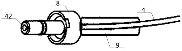
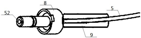
[0054] The first step: first put the bare optical fiber 41 before launching and the bare optical fiber 51 before receiving side by side and close together, then smear fluid state resin on the side walls of the bare optical fiber 41 before launching and the bare optical fiber 51 before receiving, and then put the The bare optical fiber 41 before launching and the bare optical fiber 51 before receiving resin are inserted into the long sleeve 1 until the head ends of the bare optical fiber 41 before launching and the bare optical fiber 51 before receiving pass through the first end surface X of the long sleeve 1, and the resin is cured After that, rough grinding, fine grinding, polishing, and alcohol cleaning are performed on the parts of the bare optical fiber 41 before launching and the bare optical fiber 51 before receiving that pass throu...
Embodiment 1
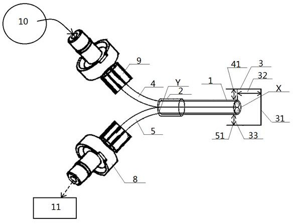
[0065] see figure 1 — Figure 6 , a reflective optical fiber displacement sensing system, comprising a transmitting optical fiber 4 and a receiving optical fiber 5, the input end of the emitting optical fiber 4 is connected to a light source 10, and the output end of the receiving optical fiber 5 is connected to a photodetector 11; The bare fiber 41 near its output end on the transmitting fiber 4 is the bare fiber 41 before receiving, and the bare fiber 51 near its input on the receiving fiber 5 is the bare fiber 51 before receiving. The bare fiber 41 before launching and the bare fiber 51 before receiving are arranged side by side. The bottom side circumference of 41 is in contact with the top side circumference of the bare optical fiber 51 before receiving; the outside of the side circumference of the bare optical fiber 41 before the emission and the bare optical fiber 51 before receiving are all wrapped with the same resin layer 6, and the outside of the resin layer 6 Wrap...
Embodiment 2
[0073] Basic content is the same as embodiment 1, the difference is:
[0074] Structurally, the outer sides of the bare optical fiber before transmitting 41 and the bare optical fiber before receiving 51 are wrapped with the same adhesive tape layer 7 , and the outer portion of the adhesive tape layer 7 is wrapped with a resin layer 6 .
[0075] In the preparation method: in the first step, the bare optical fiber 41 before emission and the bare optical fiber 51 before reception are arranged side by side and close together, and then the bare optical fiber 41 before emission and the bare optical fiber 51 before reception are wound at least Three layers of raw tape are used to obtain the tape layer 7, and then the fluid state resin is applied on the side circumference of the tape layer 7.
PUM
| Property | Measurement | Unit |
|---|---|---|
| The inside diameter of | aaaaa | aaaaa |
| Outer diameter | aaaaa | aaaaa |
Abstract
Description
Claims
Application Information
 - R&D Engineer
- R&D Manager
- IP Professional
- Industry Leading Data Capabilities
- Powerful AI technology
- Patent DNA Extraction
Browse by: Latest US Patents, China's latest patents, Technical Efficacy Thesaurus, Application Domain, Technology Topic, Popular Technical Reports.
© 2024 PatSnap. All rights reserved.Legal|Privacy policy|Modern Slavery Act Transparency Statement|Sitemap|About US| Contact US: help@patsnap.com