Circumferential illumination measurement system and measurement method

A technology of illuminance measurement and circumference, which is applied in the field of manned spaceflight systems, can solve the problems of time-consuming and laborious, inability to accurately locate measurement points, poor accuracy and repeatability, etc.

Inactive Publication Date: 2021-05-04
CHANGCHUN INST OF OPTICS FINE MECHANICS & PHYSICS CHINESE ACAD OF SCI
View PDF7 Cites 0 Cited by
  • Summary
  • Abstract
  • Description
  • Claims
  • Application Information

AI Technical Summary

Problems solved by technology

The manual test adopts the scheme of hand-held illuminance meter, uses a ruler to measure the working distance of the lighting system, uses a black curtain as the lighting background, draws a circle of field of view with a specified radius on the black curtain, and then takes 8 to 16 points on the circle, After lighting with the LED light source system, measure the illuminance of each point with an illuminance meter; due to the difference in manual operation, it is impossible to accurately locate the measurement point, and the accuracy and repeatability of the measurement are poor. The data processing adopts the method of manual reading and processing. Time-consuming
The automatic test scheme is mainly aimed at the lighting system of lamps and lanterns. The characteristic is that the motion mechanism is a linear motion mechanism. The measurement target is the illuminance within the linear stroke. Post-processing cannot be judged in real time

Method used


Image

  • Circumferential illumination measurement system and measurement method

Examples


Embodiment Construction

[0027] It should be understood that the specific embodiments described here are only used to explain the present invention, not to limit the present invention.

[0028] The following will clearly and completely describe the technical solutions in the embodiments of the present invention with reference to the accompanying drawings in the embodiments of the present invention. Obviously, the described embodiments are only part of the embodiments of the present invention, not all of them. Based on the embodiments of the present invention, all other embodiments obtained by persons of ordinary skill in the art without creative efforts fall within the protection scope of the present invention.

[0029] It should be noted that all directional indications (such as up, down, left, right, front, back...) in the embodiments of the present invention are only used to explain the relationship between the components in a certain posture (as shown in the accompanying drawings). If the specific...


PUM


Abstract

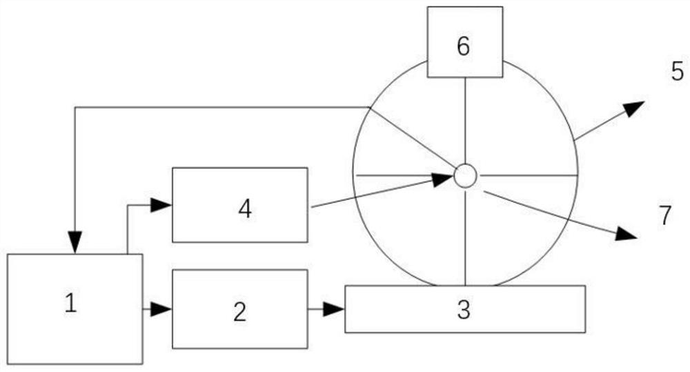
The invention belongs to the technical field of manned aerospace systems, and particularly relates to a circumferential illumination measurement system and a measurement method. The system comprises a control device, a linear servo system, a moving guide rail, a circumferential servo system, a circumferential slide rail, and an illumination measurement device. The circumferential slide rail is fixedly arranged on the moving guide rail, and the normal direction of the rotating surface of the circumferential slide rail is parallel to the linear motion direction of the moving guide rail; the illumination measurement device is fixedly arranged on the circumferential slide rail and is used for measuring illumination data of a measured light source; the circumferential slide rail rotates to drive the illumination measurement device to rotate; and the control device is used for collecting illumination data measured by the illumination measuring device and judging whether the illumination data is qualified or not. According to the measurement system and the measurement method provided by the invention, by adopting a mode of combining the linear servo system and the circumferential servo system, the position precision of illumination measurement is improved, and the measurement precision of the illumination is further increased.

Description

technical field [0001] The invention relates to the technical field of manned spaceflight systems, in particular to a circumferential illuminance measurement system and a measurement method. Background technique [0002] In the manned spaceflight system, the maintenance of astronauts out of the cabin is a necessary part of the work. In this process, the LED light source system provides lighting for the operation and maintenance space, which is an important part of the maintainability of the spacecraft. Therefore, the illuminance of the lighting system has become an important technical index. In the manned spaceflight system, the illuminance index requirements are usually the operating distance of the lighting system, the lighting radius of the lighting system, and the lower limit of the illuminance at the edge of the light. The farthest distance is 1.2m, and the minimum illuminance is not less than 500lx on the field of view circle with a radius of 0.4m. [0003] There are ...

Claims


Application Information

Patent Timeline
IPC IPC(8): G01M11/02G01J1/02
CPCG01J1/0242G01M11/0207
Inventor 宋健葛欣宏韩景壮
Owner CHANGCHUN INST OF OPTICS FINE MECHANICS & PHYSICS CHINESE ACAD OF SCI
Why Eureka
Try Eureka