Track pantograph electric spark detection system, method, medium and equipment

An electric spark and pantograph technology, applied in the field of rail transit, can solve the problems of low work efficiency, high labor cost, work errors, etc., and achieve the effects of accurate identification, high detection efficiency and cost reduction.

Pending Publication Date: 2021-05-04
桂林海威科技股份有限公司
View PDF6 Cites 1 Cited by
  • Summary
  • Abstract
  • Description
  • Claims
  • Application Information

AI Technical Summary

Problems solved by technology

The disadvantage of the existing technology is that it is necessary to manually detect the state of the electric spark, and manual detection may cause work mistakes, and the work efficiency is low, and a large amount of labor costs are required

Method used


Image

  • Track pantograph electric spark detection system, method, medium and equipment
  • Track pantograph electric spark detection system, method, medium and equipment

Examples


Embodiment 1

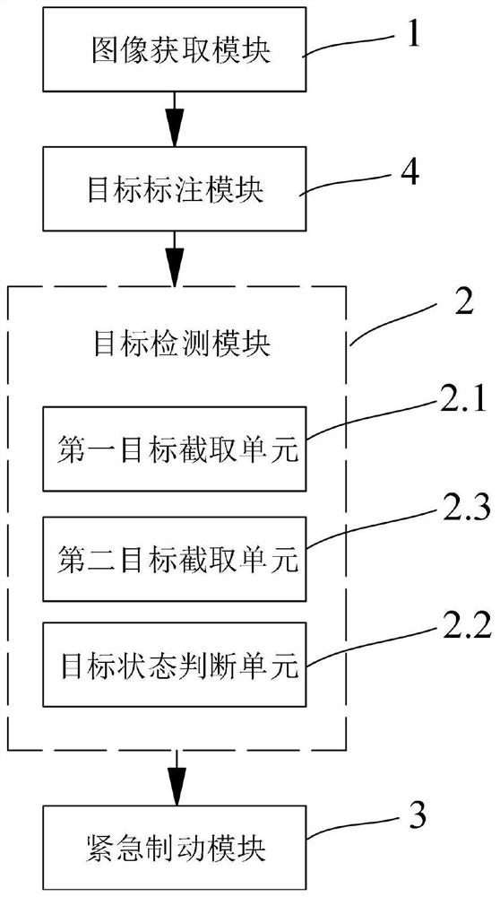
[0046] Such as figure 1 As shown, the rail pantograph electric spark real-time detection system includes:

[0047] Image acquisition module 1, the image acquisition module 1 is used to collect the video data of the pantograph on the rail train, decompose the video data into images, and generate the first image set;

[0048] Target detection module 2, the target detection module 2 is used to obtain the first image set, import the first image set into the deep learning model, use the electric spark state in the first image set to train the deep learning model, and obtain The deep learning model after training, and save model parameter; Also be used for importing the video data to be identified, decompose described video data into image, generate the second image set; Utilize the deep learning model after training to described second image The centralized electric spark state is used for reasoning, and when the electric spark state is abnormal, an alarm message is generated;

...

Embodiment 2

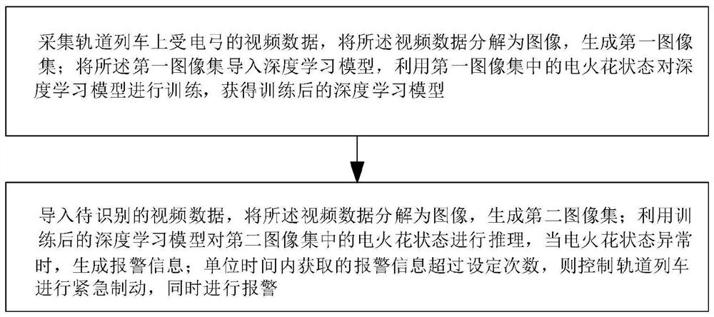
[0068] Such as figure 2 As shown, the real-time detection method for electric sparks of rail pantographs includes the following steps:

[0069] Collect video data of pantographs on rail trains, decompose the video data into images, and generate a first image set; import the first image set into a deep learning model, and use the electric spark state in the first image set to perform deep learning The model is trained, the trained deep learning model is obtained, and the model parameters are saved;

[0070] Import the video data to be identified, decompose the video data into images, and generate a second image set; use the trained deep learning model to infer the state of the electric spark in the second image set, and generate an alarm when the state of the electric spark is abnormal Information; if the alarm information obtained per unit time exceeds the set number of times, the rail train will be controlled to perform emergency braking and an alarm will be issued at the s...

Embodiment 3

[0088] The computer-readable storage medium includes instructions, and when the instructions are run on the computer, the computer is made to execute the method for real-time detection of electric sparks of rail pantographs.


PUM


Abstract

The invention relates to a rail pantograph electric spark real-time detection system and method, and the system comprises an image obtaining module which collects the video data of a pantograph on a rail train, decomposes the video data into images, and generates a first image set; the target detection module obtains a first image set, imports the first image set into the deep learning model, and trains the deep learning model by using the electric spark state in the first image set to obtain a trained deep learning model; video data to be recognized are imported, the video data are decomposed into images, and a second image set is generated; the state of the electric spark in the second image set is reasoned by using the trained deep learning model, and generating alarm information when the state of the electric spark is abnormal; and if the alarm information acquired by the emergency braking module in unit time exceeds a set number of times, emergency braking is performed, and meanwhile, an alarm is given. The electric spark detection efficiency is high, the electric spark state is accurately recognized, and the cost can be effectively reduced.

Description

technical field [0001] The present invention relates to the technical field of rail transit, in particular to a system, method, medium and equipment for real-time detection of rail pantograph electric sparks. Background technique [0002] The pantograph is the electrical equipment for the electric traction locomotive to obtain electric energy from the catenary. It is installed on the roof of the locomotive or the motor car. During the operation of the electric traction locomotive, the pantograph needs to be in contact with the catenary grid, and electric sparks are generated during the contact process. For the safe and stable operation of electric traction locomotives, real-time monitoring of electric sparks is required. [0003] The pantograph electric spark detection system in the prior art obtains electric spark images through a camera, and manually analyzes the electric spark images. The disadvantage of the prior art is that it is necessary to manually detect the state ...

Claims


Application Information

Patent Timeline
IPC IPC(8): G06K9/00G06K9/20G06K9/34G06K9/62G06N3/04G06N3/08B61L15/00B60T7/12B60L5/18
CPCG06N3/08B61L15/0081B60T7/124B60L5/18G06V20/40G06V10/22G06V10/267G06V2201/07G06N3/045G06F18/214
Inventor 覃雩悠周明资明祥张志斌王建卫覃琨
Owner 桂林海威科技股份有限公司
Why Eureka
Try Eureka