

Low-noise transformer oil tank
A technology of transformer oil tank and low noise, which is applied in transformer/inductor cooling, transformer/inductor casing, etc., and can solve problems such as excessive noise in substations
- Summary
- Abstract
- Description
- Claims
- Application Information
AI Technical Summary
Problems solved by technology
Method used
Image

Examples
Embodiment 1
[0030] The mass block can be of any shape, and it is a cylindrical additional mass in this embodiment;
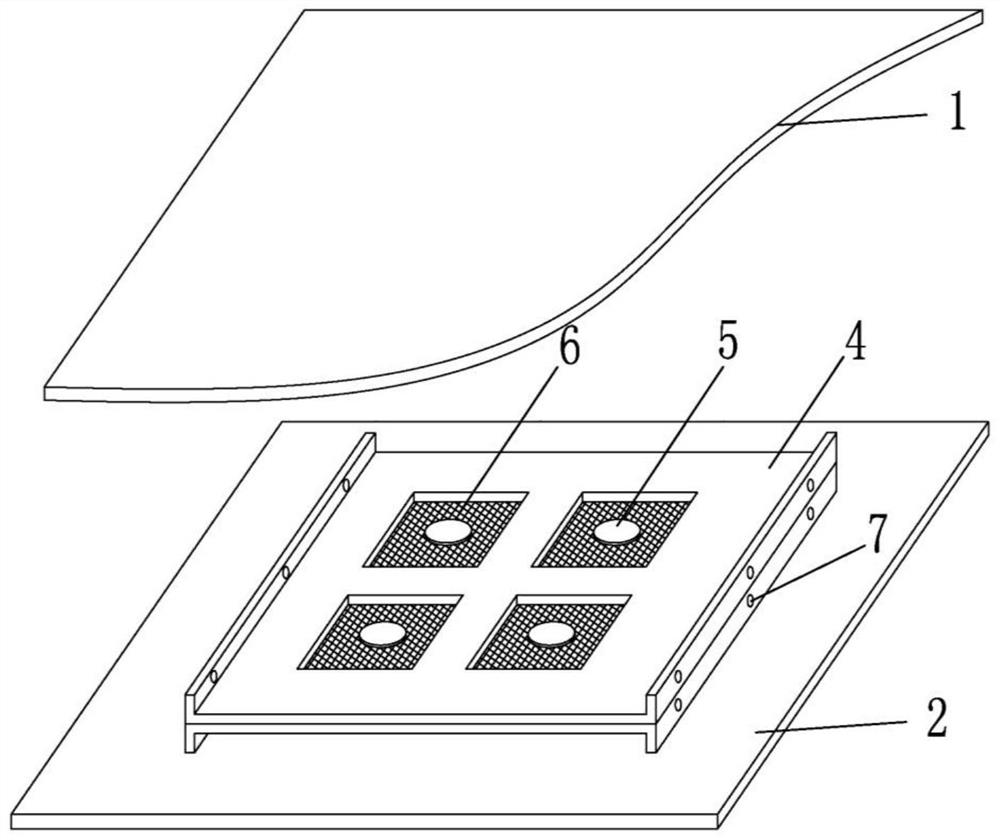
[0031] A low-noise transformer oil tank, comprising an oil tank inner wall (2), an oil tank outer wall (1), a support partition (4), a film material (6) and an additional mass (5).
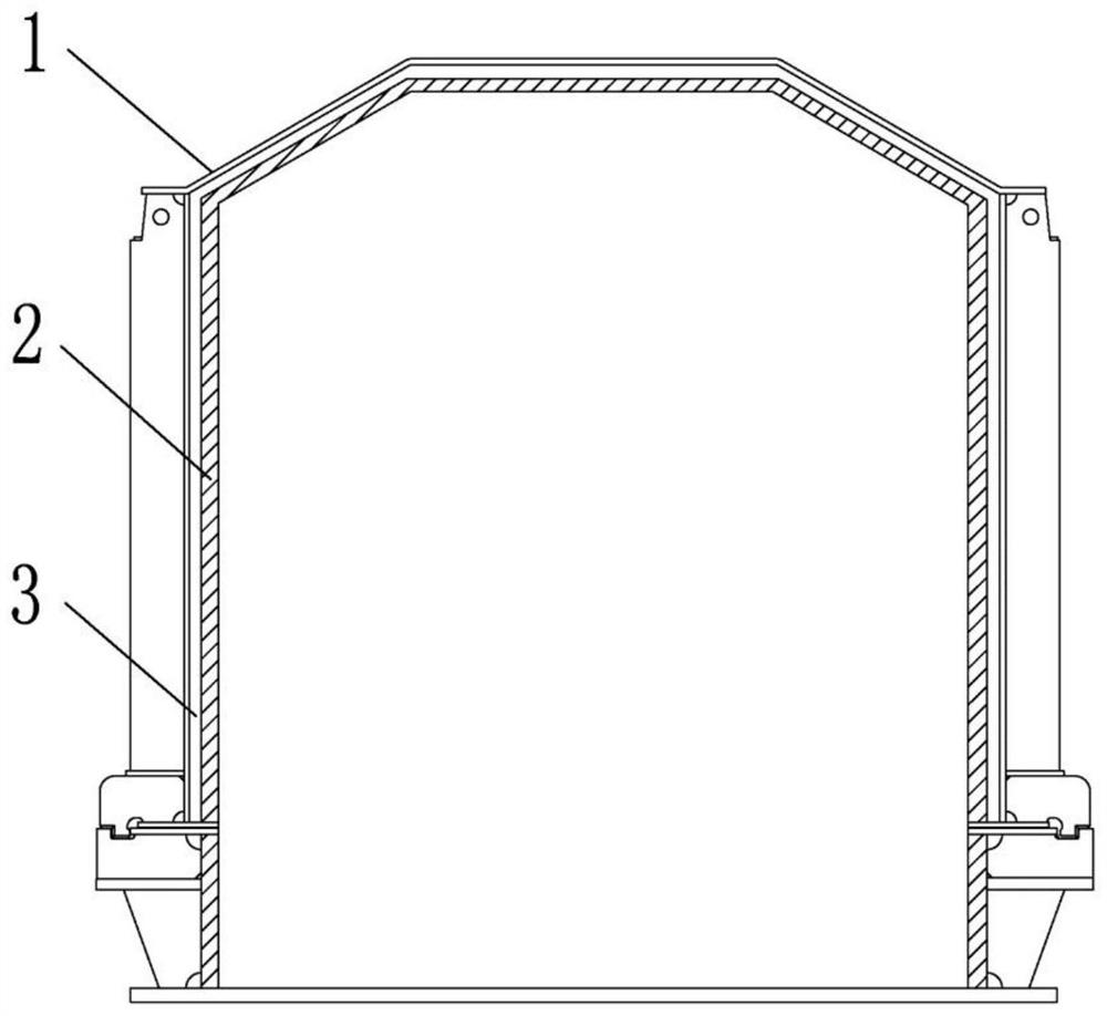
[0032] Such as figure 1 and figure 2 As shown, the inner wall (2) of the oil tank is made of steel plate, the inner wall is directly in contact with the transformer insulating oil, and the inside of the inner wall needs to be painted according to a conventional transformer.
[0033] The outer wall (1) of the fuel tank is made of steel plate, and the outer side of the outer wall is in contact with the air. It needs to be painted externally according to a conventional transformer to prevent corrosion of the steel plate and the weld.
[0034] The support partition (4) is installed in the middle of the inner and outer walls of the fuel tank through the installation bolts and the installation bol...
Embodiment 2
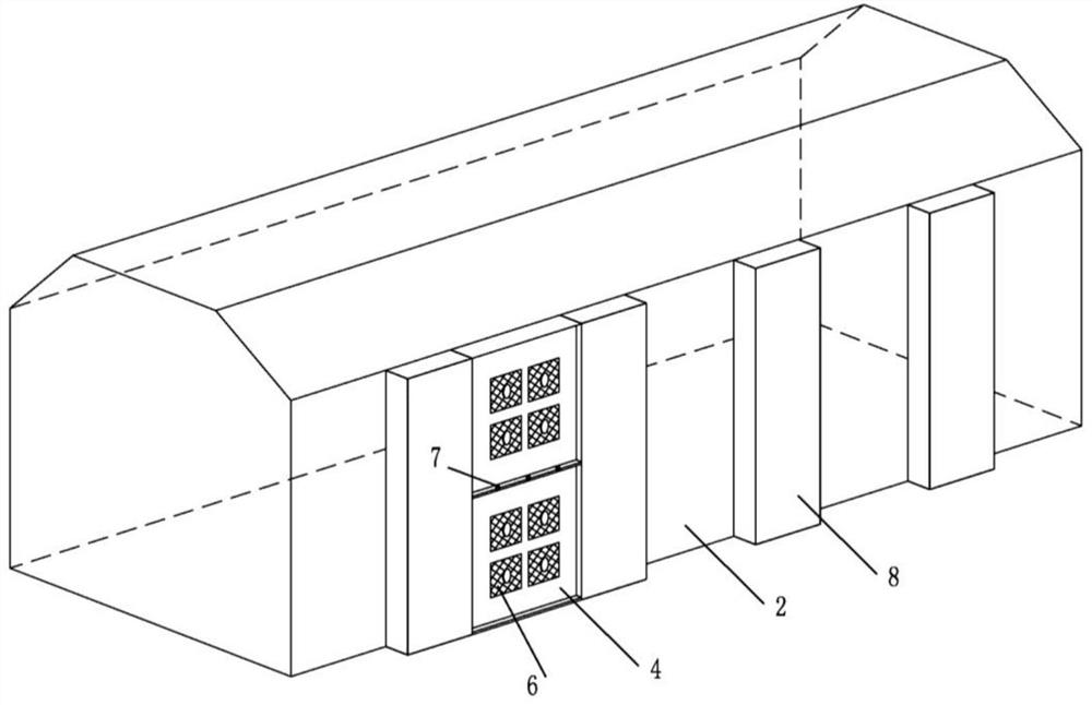
[0052] The inner box wall of the oil-immersed transformer is a steel plate with a thickness of 12mm, the outer box wall is a steel plate with a thickness of 6mm, the middle part of a single-layer supporting partition is a steel plate with a thickness of 3mm, the edge height is 10mm, the size of the partition is 200mm×200mm, and the size of the film is 50mm×50mm. The two partitions are pressed and bonded to each other. Four films are arranged on a set of supporting partitions. The mass block is 500g. They are arranged in the plane area between the inner and outer tank walls. The distance between the inner and outer tank walls is 20mm, and they are also arranged on the outer wall of the fuel tank On the outer side of the two reinforcement beams, they are arranged up and down in the groove space between the two reinforcement beams, and are connected with the reinforcement beams by welding.
Embodiment 3
[0054] According to the noise spectrum characteristics of the oil-immersed transformer, the thin film material in the supporting partition is designed, such as Figure 4 As shown, the overall diameter is 20mm, the mass block diameter is 10mm, and the thicknesses are 0.5mm, 1mm, 2mm...10mm respectively. For the sound insulation under each parameter, see Figure 5 . For the relationship between additional quality and frequency bands that can reduce noise see Figure 6 . according to Figure 6 Curve data fitting yields the following empirical formula:
[0055]f=288×m -0.5 (2)
[0056] Where m is the mass of the mass block in g, and f is the noise frequency that can be suppressed by the material.
[0057] Figure 6 Among them, D is the diameter of the mass block, and T is the thickness of the mass block.
[0058] In the embodiment, the mass of the mass block is obtained according to the noise frequency to be isolated, and the sound insulation is obtained according to the ...
PUM
| Property | Measurement | Unit |
|---|---|---|
| Thickness | aaaaa | aaaaa |
| Diameter | aaaaa | aaaaa |
| Diameter | aaaaa | aaaaa |
Abstract
Description
Claims
Application Information