Pressure relief valve, respiratory support equipment air path and respiratory support equipment

A technology that supports equipment and pressure relief valves, applied in the field of medical devices, can solve problems such as small pressure relief range, small pressure range, and increased gas resistance

Pending Publication Date: 2021-05-07
HUNAN MICOME ZHONGJIN MEDICAL SCI & TECH DEV CO LTD
View PDF1 Cites 1 Cited by
  • Summary
  • Abstract
  • Description
  • Claims
  • Application Information

AI Technical Summary

Problems solved by technology

Three-way valve control is adopted, and the inlet and outlet of the valve need to be connected to the gas circuit, which will increase the gas resistance, and only one valve is set for pressure relief, the pressure relief range is small, and the controllable pressure range is also small

Method used


Image

  • Pressure relief valve, respiratory support equipment air path and respiratory support equipment
  • Pressure relief valve, respiratory support equipment air path and respiratory support equipment
  • Pressure relief valve, respiratory support equipment air path and respiratory support equipment

Examples


Embodiment 1

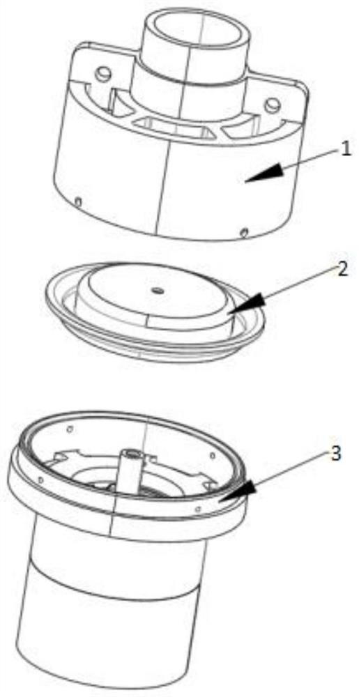
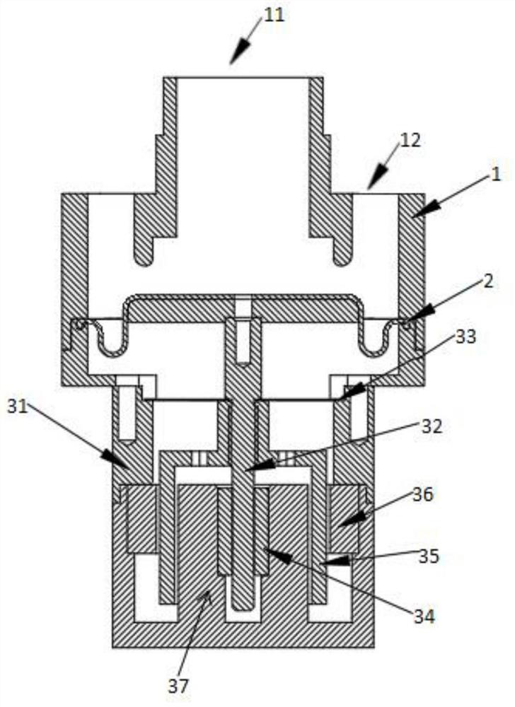
[0043] Such as Figure 1-4As shown, this embodiment provides a pressure relief valve, including a valve body 1, wherein the valve body 1 is a hollow structure provided with an air inlet 11 and a pressure relief port 12, the lower part of the valve body 1 is provided with a diaphragm 2, and the air inlet 11 communicates with the pressure relief port 12 through the space above the diaphragm 3, and the lower part of the diaphragm 2 is provided with a driving device for driving the diaphragm 2 to move up and down.

[0044] As a further improved technical solution, the air inlet 11 is located in the middle of the upper part of the valve body 1, and there are several pressure relief ports 12, and the several pressure relief ports 12 are arranged around the air inlet 11 respectively.

[0045] In one embodiment, the valve body 1 of the pressure relief valve is a cylindrical structure with a hollow interior, an air inlet 11 is arranged at the center of the upper part, and several press...

Embodiment 2

[0062] This embodiment provides an air circuit of the respiratory support equipment, wherein the air circuit of the respiratory support equipment includes a flow sensor C, a pressure sensor D and the pressure relief valve B in Embodiment 1, wherein the pressure relief valve B is arranged at the air circuit of the respiratory support equipment On the branch flow, and the number of pressure relief valves B is at least two.

[0063] In the specific implementation process, such as Figure 5 As shown, one end of the air circuit is connected to the air source A, and the other end is connected to the patient’s breathing port E. The air source A is used to provide airflow with stable pressure and flow rate. After the airflow is sent from the air source A, a branch flow is set on the air path. The other end of the pipeline is connected to the air inlet 11 of the pressure relief valve B, and then a flow sensor C and a pressure sensor D are respectively set on the air path for feedback o...

Embodiment 3

[0065] This embodiment provides a respiratory support device, wherein the respiratory support device includes the air circuit of the above respiratory support device.

[0066] The working principle of the present invention is as follows:

[0067] When the patient inhales, it is necessary to increase the pressure of the air circuit: at this time, the voice coil motor increases the output by increasing the current, and the motor shaft pushes the diaphragm to move upward, so that the space between the air inlet and the pressure relief port is reduced , the pressure relief capacity decreases, the air pressure rises, until the air pressure rises to the set value, the diaphragm stops moving upwards, and the size of the pressure relief port remains unchanged.

[0068] When the patient exhales, it is necessary to reduce the pressure of the air circuit: at this time, the voice coil motor reduces the output force by reducing the current. At this time, the pressure provided by the pressu...


PUM


Abstract

The invention provides a pressure relief valve, a respiratory support equipment air path and respiratory support equipment. The pressure relief valve comprises a valve body, wherein the valve body is of a hollow structure provided with an air inlet and a pressure relief opening, a diaphragm is arranged on the lower portion of the valve body, the air inlet communicates with the pressure relief opening through a space above the diaphragm, and a driving device is arranged on the lower portion of the diaphragm and used for driving the diaphragm to move up and down. The air inlet and the pressure relief opening are formed in the upper portion of the pressure relief valve at the same time, control over the air flow is achieved by controlling the distance between the diaphragm and the pressure relief opening, the pressure relief valve is used for being connected with a branch of the respiratory support equipment air path and connected with a main path of the air path through one air inlet, the air resistance of the respiratory support equipment air path can be reduced, pressure control is achieved by controlling the pressure relief magnitude of the pressure relief valve on the branch, two or more pressure relief valves are combined for use in the air path according to use requirements, the pressure control range is expanded, and the pressure control precision is improved.

Description

technical field [0001] The invention belongs to the technical field of medical devices, and in particular relates to a pressure relief valve, an air circuit of a breathing support device and a breathing support device. Background technique [0002] Respiratory support equipment (such as ventilator) is an instrument used to replace or assist human respiratory function. It is suitable for artificial respiration for patients with respiratory failure or even stop breathing. It is an important tool to save the lives of some critically ill patients. , has been widely used in the medical field and is deeply loved by the majority of patients. At present, the ventilator on the market uses a turbine for air supply. Due to the unstable air flow caused by the rotation of the turbine, its air supply pressure and flow rate are often unstable. , bringing discomfort to the patient. [0003] The breathing control valve is an important part of the ventilator. The existing breathing control v...

Claims


Application Information

Patent Timeline
Patent Type & Authority Applications(China)
IPC IPC(8): A61M16/20A61M16/00
CPCA61M16/202A61M16/00A61M16/0003A61M2016/0027A61M2016/003A61M2205/3331
Inventor 戴征曾棚袁越阳
Owner HUNAN MICOME ZHONGJIN MEDICAL SCI & TECH DEV CO LTD
Why Eureka
Try Eureka