Micro-channel structure, micro-fluidic chip and heterogeneous reaction method

A technology of microfluidics and flow channels, applied in the field of microfluidics, can solve problems such as difficult quantitative control

Pending Publication Date: 2021-05-07
GUANGDONG UNIV OF TECH
View PDF10 Cites 2 Cited by
  • Summary
  • Abstract
  • Description
  • Claims
  • Application Information

AI Technical Summary

Problems solved by technology

Although the dispersion of droplets (or particles) can be achieved to a certain extent, a certain length of s...

Method used


Image

  • Micro-channel structure, micro-fluidic chip and heterogeneous reaction method
  • Micro-channel structure, micro-fluidic chip and heterogeneous reaction method
  • Micro-channel structure, micro-fluidic chip and heterogeneous reaction method

Examples


Embodiment 2

[0087] The above is the embodiment one provided by the application, and the following is the embodiment two provided by the application, specifically:

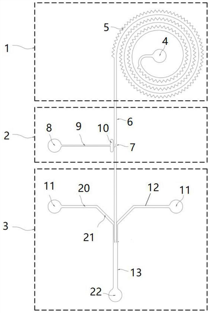
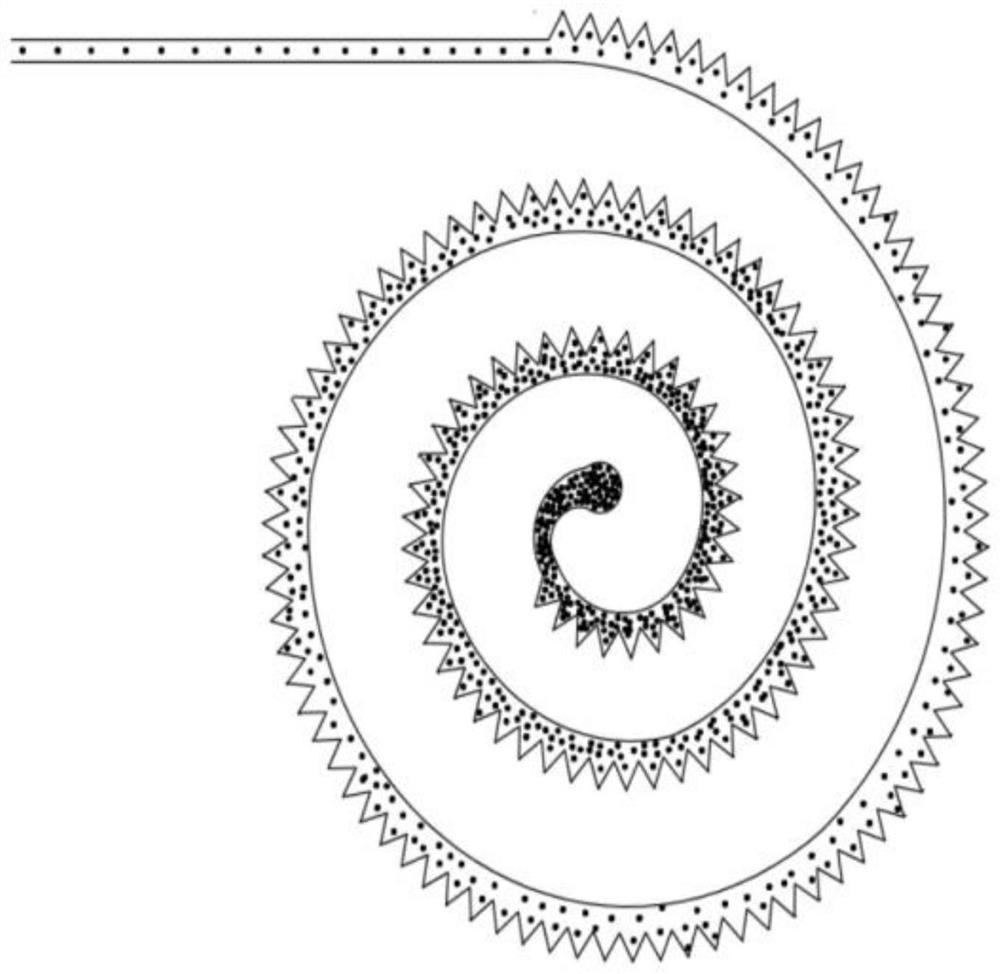
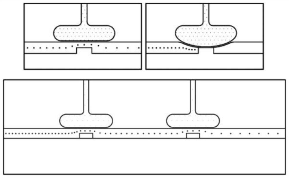
[0088] The material of the chip body is PDMS, in which the length of the continuous outer triangular expansion focusing channel 5 is 1000 mm, the distance between two adjacent vortex focusing channels is 150 μm, and the radius of curvature of the innermost channel is 20 mm. The gas phase channel and the reaction liquid phase channel The width of 12 is 50 μm, the width of continuous liquid phase flow channel 6 is 100 μm, the width of mixed liquid phase flow channel 13 is 200 μm, the distance between gas buffer chamber 10 and liquid phase flow channel wall is 40 μm, and the height of all flow channels is 100 μm. Nitrogen gas was selected as the gas phase, 50% alcohol solution containing polystyrene microspheres with a particle size of 30 μm was used as the sample solution, and deionized aqueous solution was used as the reaction s...

Embodiment 3

[0089] The above is the second embodiment provided by the application, and the following is the third embodiment provided by the application, specifically:

[0090] The material of the chip body is PDMS, in which the length of the continuous outer triangular expansion focusing channel 5 is 1100 mm, the distance between two adjacent vortex focusing channels is 130 μm, and the radius of curvature of the innermost channel is 15 mm. The gas phase channel and the reaction liquid phase channel The width of 12 is 60 μm, the width of continuous liquid phase flow channel 6 is 100 μm, the width of mixed liquid phase flow channel 13 is 180 μm, the distance between gas buffer chamber 10 and liquid phase flow channel wall is 50 μm, and the height of all flow channels is 100 μm. Nitrogen gas was selected as the gas phase, a modified titanium dioxide solution with a particle size of 50 μm was used as the sample solution, and a deionized aqueous solution was used as the reaction sample solutio...


PUM


Abstract

The invention provides a micro-channel structure, a micro-fluidic chip and a heterogeneous reaction method. The micro-channel structure comprises a continuous outer triangular expansion focusing unit, an active valve quantitative uniform control unit and a coaxial flow heterogeneous reaction unit, the continuous outer triangular expansion focusing unit comprises a continuous liquid phase sample inlet, a continuous outer triangular expansion focusing runner and a continuous liquid phase runner; the active valve quantitative uniform control unit comprises a runner built-in valve plug, a gas phase sample inlet, a gas phase channel and a gas buffer chamber; a built-in valve plug is arranged on the inner wall of the continuous liquid phase flow channel; and the coaxial flow heterogeneous reaction unit comprises a reaction liquid phase sample inlet, a reaction liquid phase flow channel and a mixed liquid phase flow channel. The invention solves the technical problem of how to design a microfluidic device and an operation process to realize rapid and accurate quantitative control for accurate and efficient heterogeneous reaction on the basis of generating high-dispersion liquid drops and particles.

Description

technical field [0001] The present application relates to the field of microfluidic technology, in particular to a microfluidic channel structure, a microfluidic chip and a heterogeneous reaction method. Background technique [0002] With the development of science and technology, more and more fields (energy, immunity, biochemistry, etc.) need to use miniaturized reaction methods for highly dispersed micro-precision operations. Microfluidic technology can achieve many difficult-to-complete micro-processing and micro-operations. has received widespread attention. Microfluidics is the use of microchannels and devices to manipulate tiny particles (or samples) that cannot be achieved by conventional methods. It can integrate biological detection, a series of biochemical reactions, and various sample preparations into tiny chips for special operations, and has broad application prospects in many fields. [0003] At present, the conventional preparation process of liquid drople...

Claims


Application Information

Patent Timeline
IPC IPC(8): B01J19/00B01J4/02B01J4/00B01L3/00
CPCB01J19/0093B01J19/0053B01J4/02B01J4/008B01L3/502738
Inventor 王超蒋志强
Owner GUANGDONG UNIV OF TECH
Why Eureka
Try Eureka